Installation Instructions Cat. No.
ArmorBlock 8 Input Module European Union Directive Compliance If this product is installed within the European Union or EEA regions and has the CE mark, the following regulations apply.
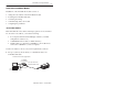
ArmorBlock 8 Input Module 3 Install Your ArmorBlock Module Installation of the ArmorBlock module consists of: • • • • • setting the node address in the ArmorBlock module mounting the ArmorBlock module connecting the wiring communicating with your module configuring the parameters Set the Node Address Each ArmorBlock comes with its internal program set for node address 63.
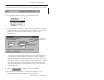
ArmorBlock 8 Input Module 2. Using DeviceNet Manager Software, go online using the “Setup Online Connection” selection on the utility pulldown menu. 3. The DeviceNet Driver selection screen appears. Select the driver for your application and click on 4. The Driver configuration screen lets you: • set the data rate • set the interface adapter node address • select the interface adapter serial port • set interface adapter baud rate Click on to go online. Publication 1792-5.2 – October 1996 .
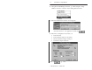
ArmorBlock 8 Input Module 5 5. The bar at the bottom of the screen will tell you when you go online. 6. At the utility pulldown, select “Node Commissioning.” 7. You can set the node address on the “Device Configuration – Node Commissioning” screen. Note that the node address “out of the box” setting is 63. Set the desired node address per your system requirements. Set new node address here. You can also set the data rate on this screen, if required.
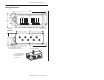
ArmorBlock 8 Input Module Mount the ArmorBlock Module Mount the block module directly to the machine or device. Complete mounting dimensions are shown below. Note that the block dimensions allow direct connection of a T-port tap (cat. no. 1485P-P1N5-j) to the DeviceNet connector. (Refer to publication 1485-6.7.1 for cabling details.) The ArmorBlock module has a sloping top and a gap at the rear to allow water or other liquids to run off during washdowns.
ArmorBlock 8 Input Module 7 Mounting Dimensions 7.25 (184.2) 3.055 (77.6) INPUT FAULT ARMORBLOCK I/O 1792-IB8 DATA RATE 1.90 (48.3) NODE ADDRESS MOD/NET STATUS 4 mounting holes for #10 screws Inches (Millimeters) 6.24 (158.5) 2.63 2.5 (66.7) (63.5) 7.74 (196.6) Block dimensions allow T-port tap connection directly onto connector Direction of liquid flow For washdown installations, or excessively moist areas, mount block with micro connectors down. Publication 1792-5.
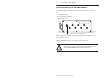
ArmorBlock 8 Input Module Connect the Wiring to the ArmorBlock Module The block module uses quick disconnect, screw-on style connectors for: • I/O input wiring • the DeviceNet connector DeviceNet mini connector 0 2 1 4 3 6 5 7 8 micro connectors for signal wiring Micro plugs are included with your module. Use these plugs to cover and seal unused ports. Pinout diagrams for these connectors are shown below.
ArmorBlock 8 Input Module 9 Connecting the Input Wiring Connect input wiring to the micro connectors which screw into mating connectors on the side of the block. Make connections as shown below. I/O Input Micro Connector Pin 1 = Sensor Source Voltage Positive 4 Pin 2 = Not used 1 3 Pin 3 = Negative/Return 2 Pin 4 = Signal (View into socket) Connecting the DeviceNet Wiring Connect DeviceNet wiring to the 5-pin mini connector on the end of the block. Connections are shown below.
ArmorBlock 8 Input Module Communicate with Your ArmorBlock Module This ArmorBlock module acts as a slave in a master/slave environment. It is both a “polled device” and a “change of state device.” When configured as a polled device, a master initiates communication by sending its polled I/O message to the ArmorBlock module. The 8 input module scans the inputs and fault bit producing a response that reflects their status.
ArmorBlock 8 Input Module 11 Configure Your Armor Module Offline Using the DeviceNet Manager Configuration Tool To configure your ArmorBlock module offline: • add the device to the network • set the parameters for the device • save the parameters to a file Note: You cannot actually configure your device offline. You can set and save the parameters to a file for downloading to the device when you go online. Publication 1792-5.
ArmorBlock 8 Input Module Adding a Device to the Network Action Response At the network screen, click on the “add device” button. At the “add device to network” screen, click on “discrete I/O” in the device type box. Then click on the desired ArmorBlock device. Select the device node address for this device. Click on the OK button when you have selected your device. Add more devices as necessary. Publication 1792-5.
ArmorBlock 8 Input Module 13 Configure your Device Parameters After adding the devices to the network, you must configure them. You have 2 choices: • highlight the device, and click on the button, or • double-click on the device to bring up the device configuration screen. The software displays the parameter status. For detailed device information on this device, click on Publication 1792-5.2 – October 1996 .
ArmorBlock 8 Input Module Configuring the Parameters Default settings for the 8 input module are: autobaud when enabled, matches device baud rate to network baud rate at powerup enable off to on delay time from a valid input signal to recognition by the block module 0ms delay on to off delay time from input signal dropping below the valid level to recognition by the block module 0ms delay reset faulted I/O reset sensor source voltage nothing selected 1.
ArmorBlock 8 Input Module 15 3. For help about a specific parameter, click on . A screen similar to this will appear. To continue, click on 4. Continue with any additional parameters you want set for your block module. For the 8 input module, additional parameters include: off-to-on delay, on-to-off delay and reset faulted I/O. When you have completed each parameter selection, click on the button. This returns you to the device configuration screen.
ArmorBlock 8 Input Module Saving to a File 1. To save those parameters to a file, click on the button. You see this screen. 2. Choose the file name, file type (.dcf), directory, and drive to which you want to save the file. 3. Click on the button to save. Printing to a Text File 1. If you choose to save your changes to a text file, click on the button. A screen similar to the following will appear. Publication 1792-5.
ArmorBlock 8 Input Module 17 2. Choose the file name, file type (.TXT), directory and drive to which you want to save the file. button to save. Use this file to print out as 3. Click on the hard copy for future reference. Online Help Online help is available on all screens. Click on to bring up pertinent information concerning the device configuration you are selecting. Additionally, help is available on each parameter screen by clicking on .
ArmorBlock 8 Input Module 2. The configuration screen for your selected driver appears. You can: • • • • set the node address set the data rate select the interface adapter serial port set the interface adapter baud rate 3. After setting the parameters, click on the button. The system will automatically go online, as shown at the bottom of the screen. Online will also appear in the Network area. Publication 1792-5.
ArmorBlock 8 Input Module 19 Add the Device to the Network Action Response At the network screen, click on the “add device” button. At the “add device to network” screen, click on “discrete I/O” in the device type box. Then click on the desired ArmorBlock device. Select the device node address for this device. Click on the OK button when you have selected your device. Add more devices as necessary.
ArmorBlock 8 Input Module 4. Click once on the device you wish to configure on the project screen . and choose The device configuration screen appears. If you have Not previously modified default settings Modified parameters but have not saved them Modified and saved parameter settings Clicked on “Load from File” Clicked on “Load from Device” Publication 1792-5.
ArmorBlock 8 Input Module 21 5. Load parameters. If you want to load parameters From a file Choose You see this screen. Choose the drive, file type, and directory to load the file from. Select the file name so that it is highlighted and choose Note: The product code, type and revision must be identical in order to load a file from one device to another. From the selected device From default settings Publication 1792-5.
ArmorBlock 8 Input Module 6. Modify the parameter. If you want to Modify a parameter Choose You see a screen similar to this one. Click on the settings you wish to activate.
ArmorBlock 8 Input Module 23 7. Save parameters to a file, to the device, or print to a file. If you want to Save parameters to a file Choose You see this screen. Select the drive, file type, directory, and file name to which you would like to save and choose Save parameters to the selected device Print to a file You see this screen. Select the drive, file type, directory, and file name to which you would like to save and choose 8. To exit from the Enhanced Configuration screen, .
ArmorBlock 8 Input Module Monitoring Parameters Online You can monitor parameters at the Device Configuration screen or at the selected parameter screen. The start monitor button on the Device Configuration screen allows you to monitor all of the parameters online. To monitor parameters: Click on the button to start the monitor. The monitor function starts after a few seconds. 1. The status line flashes “monitoring.” 2.
ArmorBlock 8 Input Module 25 Reset Faults There are various ways to reset faults on an ArmorBlock module. • cycle power to the module by disconnecting, then reconnecting the DeviceNet connector • use the Reset Faulted I/O feature on the parameter screen • use the explicit message program control feature Note: This module contains a circuit to protect the DeviceNet power supply from short circuits in an attached sensor or sensor cable.
ArmorBlock 8 Input Module The device configuration screen appears. Select the Reset Faulted I/O parameter. After selecting the parameter, click on the modify parameter button. The configuration screen for the selected parameter appears. 1. Click on the desired selection to reset. 2. Then click on the OK button to apply. 3. You will be returned to the configuration screen. Click on ”Save to Device” to apply the change. Publication 1792-5.
ArmorBlock 8 Input Module 27 Reset Faults using Explicit Message Program Control You can also reset inputs using the Explicit Message Program Control feature on the Scanner module master. Refer to the specific scanner publications for information on using this feature.
ArmorBlock 8 Input Module Configure Your Armor Module Using EDS Files Current versions of DeviceNet Manager software include ArmorBlock module support. If you are using a version of DeviceNet Manager software that does not include ArmorBlock module Electronic Data Sheets (EDS) files in its library, you can use the following information to create the file. If you are using a configuration tool other than DeviceNet Manager, you can also use the following information to create the EDS file.
ArmorBlock 8 Input Module 29 $$$$$$$$$$$$$$$$$$$$$$$$$$$$$$$$$$$$$$$$$$$$$$$$$$$$$$$$$$$$$$$$$$$$$ $$$$$$$$$$ Param1 = $ Disable Autobaud 0, $ reserved 6, $ Link Path Size ”20 03 24 01 30 64”, $ Link Path to disable autobaud attribute. 0x0002, $ No support for settable path, scaling, scaling links, or $ real time update of value. Value is gettable and $ Settable. Enumerated strings are supported.
ArmorBlock 8 Input Module $$$$$$$$$$$$$$$$$$$$$$$$$$$$$$$$$$$$$$$$$$$$$$$$$$$$$$$$$$$$$$$$$$$$$ $$$$$$$$$$ Param4 = $ Reset Faulted I/O 0, $ reserved 6, $ Link Path Size ”20 0F 24 04 30 01”, $ Link Path to param instance. 0x0002, $ No support for settable path, scaling, scaling links, $ or real time update of value. Value is gettable and $ Settable. Enumerated strings are supported.
ArmorBlock 8 Input Module 31 0, 6, ”20 08 24 03 30 03”, 0x0030, $ reserved $ Link Path Size $ Link Path to Input 3 value attribute. $ No support for settable path, scaling, or scaling $ links. $ Value is gettable only. $ Enumerated strings are not supported. 8, $ Data Type – unsigned short int 1, $ Data Size – (in bytes) ”Input 3 Value”, $ Parameter Name ””, $ Units String $$$$$$$$$$ Help string $$$$$$$$$$$ ”This parameter is the current value of Input 3.
ArmorBlock 8 Input Module 0x0030, $ No support for settable path, scaling, or scaling $ links. $ Value is gettable only. Enumerated strings are not $ supported. 8, $ Data Type – unsigned short int 1, $ Data Size – (in bytes) ”Input 6 Value”, $ Parameter Name ””, $ Units String $$$$$$$$$$ Help string $$$$$$$$$$$ ”This parameter is the current value of Input 6.
ArmorBlock 8 Input Module 33 $ Value is gettable only. $ Enumerated strings are supported.
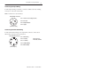
ArmorBlock 8 Input Module Troubleshoot with the Indicators The ArmorBlock I/O module has 3 types of indicators: • Mod/Net status indicator • Input fault indicator • individual I/O status indicators Mod/Net Status Indicator Input Fault Indicator INPUT FAULT ARMORBLOCK I/O 1792-IB8 DATA RATE NODE ADDRESS MOD/NET STATUS Input I/O Status Indicators Note: This module contains a circuit to protect the DeviceNet power supply from short circuits in an attached sensor or sensor cable.
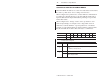
ArmorBlock 8 Input Module 35 Specifications 8 Input Module – Cat. No. 1792-IB8 Input Specifications Inputs per Block 8 sinking On-state Voltage Range 10–30V dc On-state Current Maximum Minimum 6.0mA @ 30V dc 2.0mA @ 10V dc Off-state Voltage Maximum 5V dc Off-state Current Minimum 1.5mA Transition Voltage 5–10V dc Transition Current 1.5–3.
ArmorBlock 8 Input Module General Specifications Environmental Conditions Operational Temperature Storage Temperature Relative Humidity Shock Operating Non-operating Vibration –25 to 70oC (–13 to 158oF) –40 to 85oC (–40 to 185oF) up to 100% 30 g peak acceleration, 11(+1)ms pulse width 50 g peak acceleration, 11(+1)ms pulse width Tested 10 g @ 10–500Hz per IEC 68-2-6 Conductors Refer to publication 1485-6.7.1 for information on cabling for your DeviceNet module.