Installation Instructions CompactBlock Distributed I/O on Remote I/O Series D (Cat. No. 1791R-16B0, -0B16P, -8B8P, -4B4P, -8V8P) 1791R CompactBlock™ I/O modules are stand-alone 24V dc Block I/O products that communicate via a Remote I/O link. Each Remote I/O node consists of either one base module or one base module and one expansion module. Any expansion module can be coupled with any base module. CompactBlock 1791R consists of only base modules.
CompactBlock Distributed I/O on Remote I/O Series D Any illustrations, charts, sample programs, and layout examples shown in this publication are intended solely for purposes of example. Since there are many variables and requirements associated with any particular installation, Allen-Bradley does not assume responsibility or liability (to include intellectual property liability) for actual use based upon the examples shown in this publication. Allen-Bradley publication SGI-1.
CompactBlock Distributed I/O on Remote I/O Series D 3 Environment and Enclosure This equipment is intended for use in a Pollution Degree 2 industrial environment, in overvoltage Category II applications (as defined in IEC publication 60664-1), at altitudes up to 2000 meters without derating. This equipment is considered Group 1, Class A industrial equipment according to IEC/CISPR Publication 11.
CompactBlock Distributed I/O on Remote I/O Series D Rockwell Automation Support Rockwell Automation provides technical information on the web to assist you in using our products. At http://support.rockwellautomation.com, you can find technical manuals, a knowledge base of FAQs, technical and application notes, sample code and links to software service packs, and a MySupport feature that you can customize to make the best use of these tools.
CompactBlock Distributed I/O on Remote I/O Series D 5 Installing CompactBlock I/O Follow these steps, to install the 1791R I/O module: 1. Set the Node Address on the Base Module. 2. Mount the Block(s). 3. Connect the Input/Output Wires to the Block. 4. Connect the RIO Cable. 5. Select termination for the module. 6. Connect power to the module. 7. Remove the terminal block. 8. Insert the terminal block. 9. Communicate with the 1791R Module. These steps are explained in detail in the following procedures.
CompactBlock Distributed I/O on Remote I/O Series D Set the Node Address on the Base Module The node address for network connection is set using two 8-bit DIP switches. To set the node address, lift the door containing the status LEDs on the top left side of the module. The switches are read at module power up only. The rack address setting and the starting quarter setting are described below. IMPORTANT It is important to monitor the rack fault bit.
CompactBlock Distributed I/O on Remote I/O Series D 7 DIP Switch Settings The 1791R DIP switches are described in the table below. DIP Switch Description Starting Quarter Starting Quarter SW1-2 SW1-1 Module Group Starting Quarter 0 0 0 (1st) 0 1 2 (2nd) 1 0 4 (3rd) 1 1 6 (4th) SW1 DIP Switch SW1 No. Description 3 Rack Address 4 Rack Address 5 Rack Address 6 Rack Address 7 Rack Address 8 Rack Address See table below.
CompactBlock Distributed I/O on Remote I/O Series D Rack addresses are listed in the table below.
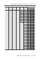
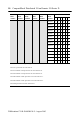
CompactBlock Distributed I/O on Remote I/O Series D 1747-SN Rack Number 1771-SN Rack Number PLC-2 Rack Number PLC-5 Rack Number PLC5/250 Rack Number PLC-3 Rack Number SW1 Switch Position 8 7 6 5 4 3 Rack 30 Rack 30 0 1 1 0 0 0 Rack 31 Rack 31 0 1 1 0 0 1 Rack 32 Rack 32 0 1 1 0 1 0 Rack 33 Rack 33 0 1 1 0 1 1 Rack 34 Rack 34 0 1 1 1 0 0 Rack 35 Rack 35 0 1 1 1 0 1 Rack 36 Rack 36 0 1 1 1 1 0 Rack 37 Rack 37 0 1 1 1 1 1 Rack 40 1 0
CompactBlock Distributed I/O on Remote I/O Series D 1747-SN Rack Number 1771-SN Rack Number PLC-2 Rack Number PLC-5 Rack Number PLC5/250 Rack Number Rack address 77 is an illegal configuration. PLC-5/11 processors can scan rack 03. PLC5/15 and PLC-5/20 processors can scan racks 01-03. PLC5/25 and PLC-5/30 processors can scan racks 01-07. PLC5/40 and PLC-5/40L processors can scan racks 01-17. PLC5/60 and PLC-5/60L processors can scan racks 01-27. PLC5/250 processors can scan racks 00-37.
CompactBlock Distributed I/O on Remote I/O Series D 11 DIP Switch No. Description 1 Comm Rate 2 Comm Rate 3 SW2 ON 00=57.6K 10=230.4K OFF 01=115.2K 11=230.
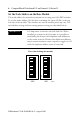
CompactBlock Distributed I/O on Remote I/O Series D Panel Mounting 1. Place the module against the panel where you want to mount it. 2. Drill holes in the panel that are aligned with mounting holes on the module. 3. Place screws through each of the 2 mounting holes and tighten until the module is firmly in place. Base Module 141 mm 5.55 in 01 2 34 56 7 Status Comm Remote I/O Allen-Bradley 01 2 3456 7 41 mm 1.
CompactBlock Distributed I/O on Remote I/O Series D 13 3. Push up on the locking lever to secure the block to the rail when block is flush against the rail. Connecting an Expansion Module to a Base Module ATTENTION ! Expansion blocks should not be installed when power is applied to the base. Carefully read the section on I/O images for 1791R base modules starting on page 22 to change produce and consume data sizes. IMPORTANT 1. Remove the expansion covers from both the base and expansion modules. 2.
CompactBlock Distributed I/O on Remote I/O Series D 4. Plug the expansion cable into both the base and expansion modules. IMPORTANT The expansion cable can only be connected to the modules such that the red stripe on the cable is on top as shown below. Red strip must be on top of ribbon cable. 012 3456 7 Status Comm Allen-Bradley Remote I/O 012 3456 7 CompactBlock I/O 1791R-8V8P 8 INPUTS / 8 OUTPUTS - DC POWER 30360 5. Replace the expansion covers on both modules.
CompactBlock Distributed I/O on Remote I/O Series D 15 Output Wiring Diagram for 1791R-0B16P and 1791D-0B16PX Modules VDC OUT 0 GND OUT 2 OUT 1 OUT 4 OUT 3 OUT 6 OUT 5 VDC OUT 7 OUT 8 GND OUT 10 OUT 9 OUT 12 OUT 11 OUT 14 OUT 13 Not Used OUT 15 + Load - 41669 Input Wiring Diagram for 1791R-16B0 and 1791D-16B0X Modules VDC GND IN 0 IN 2 IN 1 IN 3 IN 4 IN 5 IN 6 IN 7 VDC GND IN 8 IN 10 IN 9 IN 11 IN 12 IN 13 IN 14 Not Used IN 15 + 41671 Publication 1791R-IN002B-E
CompactBlock Distributed I/O on Remote I/O Series D Wiring Diagram for the 1791R-8B8P Module VDC IN 0 GND IN 4 IN 2 IN 1 IN 3 IN 6 IN 5 VDC IN 7 OUT 0 OUT 2 OUT 1 GND OUT 4 OUT 3 Not Used OUT 6 OUT 5 OUT 7 + - Load + - 41672 Wiring Diagram for the 1791R-4B4P Module IN 0 VDC GND VDC IN 1 VDC IN 2 IN 3 VDC VDC VDC + + - - OUT 0 GND Publication 1791R-IN002B-EN-P - August 2003 GND OUT 1 GND OUT 2 GND OUT 3 Not Used GND Load 42344
CompactBlock Distributed I/O on Remote I/O Series D 17 Wiring Diagram for the 1791R-8V8P Module IN 0 VDC GND IN 2 IN 1 IN 4 IN 3 IN 6 IN 5 VDC OUT 0 GND IN 7 + - - + OUT 2 OUT 1 OUT 4 OUT 3 OUT 6 OUT 5 Not Used OUT 7 Load 42346 Output Wiring Diagram for 1791D-0V16PX Module OUT 0 VDC GND OUT 2 OUT 1 - OUT 4 OUT 3 OUT 6 OUT 5 VDC OUT 8 GND OUT 7 OUT 10 OUT 9 OUT 12 OUT 11 OUT 14 OUT 13 Not Used OUT 15 Load + 41726 Input Wiring Diagram for 1791D-16V0X Module
CompactBlock Distributed I/O on Remote I/O Series D Connect the Remote I/O Terminal Connector Refer to the following information when connecting the Remote I/O terminal connector to the 1791R block I/O. If you connect or disconnect the serial cable with power applied to this module or the serial device on the other end of the cable, an electrical arc can occur. This could cause an explosion in hazardous location installations. Be sure that power is removed or the area is nonhazardous before proceeding.
CompactBlock Distributed I/O on Remote I/O Series D 19 Select Termination for the Module The terminator resistor is provided in the module. Use the DIP switches to select termination for the module. See below. Line 1 SW2 SW1 82 ohm 150 ohm Line 2 Switch SW1 SW2 ON Terminator on *1 Terminator on **2 OFF No Terminator No Terminator * 1 at baud rate 230.4KBPS. **2 at baud rate 57.6KBPS or 115.2KBPS.
CompactBlock Distributed I/O on Remote I/O Series D Connect Power to the Module To apply power to the 1791R module, refer to the illustration below. Module power connector COM GND +24V 43108 Pin Number Name 1 Com (24V dc return) 2 Gnd (Field ground) 3 +24V dc Remove the Terminal Block WARNING ! When you connect or disconnect the Removable Terminal Block (RTB) with field side power applied, an electrical arc can occur. This could cause an explosion in hazardous location installations.
CompactBlock Distributed I/O on Remote I/O Series D 21 2. Lift the terminal block out of the base. Retaining Screw VDC Re S Co tatu mm s mo RIO te IN0 IN2 IN4 GND IN1 IN3 0 I/O 1 2 3 4 IN5 Retaining Screw IN6 VDC IN8 IN7 GND IN9 5 6 IN1 0 IN 1 IN11 7 0 1 2 3 4 5 2 IN 14 Not 3 IN Used 15 IN1 6 7 43106 Insert the Terminal Block Follow the directions below to insert the CompactBlock terminal block. 1.
CompactBlock Distributed I/O on Remote I/O Series D Communicate With the 1791R Module Determine the Baud Rate for Your Remote I/O Connection Use the DIP switches to set the baud rate before you power up the module. Refer to the following table for baud rate specifications. Baud Rate Cable Length 57.6KBPS 3048m 115.2KBPS 1524m 230.
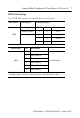
CompactBlock Distributed I/O on Remote I/O Series D 23 0B16P 17 16 15 14 13 12 11 10 Input Image Reserved Input Image Reserved Output Image O 15 O 14 O 13 O 12 O 11 O 10 O 9 Output Image O 8 7 6 5 4 3 2 1 0 O 7 O 6 O 5 O 4 O 3 O 2 O 1 O 0 Reserved 8B8P/8V8P 17 16 15 Input Image 14 13 12 11 10 Reserved Input Image 7 6 5 4 3 2 1 0 In 7 In 6 In 5 In 4 In 3 In 2 In 1 In 0 O 7 O 6 O 5 O 4 O 3 O 2 O 1 O 0 7 6 5 4 3 2 1 0 In 3 In 2
CompactBlock Distributed I/O on Remote I/O Series D The following examples are for 1791 Remote I/O base modules with expansion modules.
CompactBlock Distributed I/O on Remote I/O Series D 25 8B8P with 16BOX or 8V8P with 16VOX Input Image 17 16 15 14 13 12 11 10 7 6 5 4 3 2 1 0 EX In 7 EX In 6 EX In 5 EX In 4 EX In 3 EX In 2 EX In 1 EX In 0 In 7 In 6 In 5 In 4 In 3 In 2 In 1 In 0 Input Image Reserved Ex In 15 E X In 14 E X In 13 EX In 12 EX In 11 E X In 10 EX In 9 EX In 8 Output Image Reserved O 7 O 6 O 5 O 4 O 3 O 2 O 1 O 0 7 6 5 4 3 2 1 0 In 7 In 6 In 5 In 4 In 3 In 2 In 1
CompactBlock Distributed I/O on Remote I/O Series D 4B4P with 0B16PX 17 16 15 14 13 12 Input Image 11 10 7 6 5 4 Reserved Input Image 3 2 1 0 In 3 In 2 In 1 In 0 O 3 O 2 O 1 O 0 E X O 15 E X O 14 E X O 13 E X O 12 Reserved Output Image EX O 11 EX O 10 EX O 9 EX O 8 EX O 7 EX O 6 Output Image EX O 5 EX O 4 EX O 3 E X O 2 E X O 1 EX O 0 Reserved Following are data tables for internal usage between base and expansion modules.
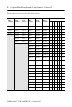
CompactBlock Distributed I/O on Remote I/O Series D 27 Maximum Output Data Format (Base Modules -0B16P or -0V16P) Bit Position Word 0 15 14 13 12 11 10 9 8 7 6 5 4 3 2 1 0 O15 O14 O13 O12 O11 O10 O9 O8 O7 O6 O5 O4 O3 O2 O1 O0 1 Reserved Analog Output Data Channel 0 2 Reserved Analog Output Data Channel 1 3 OM x OR x IM x IR x IF R HLS OE OE HLS R IF IR3 IR2 IR1 IR0 Base IM3 IM2 IM1 IM0 OR1 OR0 OM1 OM0 Output Mode Selection Set “0”: Voltage Mode Set “1”: Cur
CompactBlock Distributed I/O on Remote I/O Series D Maximum Output Data Format (Base Modules -16B0) Bit Position Word 15 0 1 2 14 13 12 11 10 9 8 7 Reserved Reserved OE HLS 6 4 3 2 1 0 OR1 OR0 OM1 OM0 4 3 Analog Output Data Channel 1 R IF IR3 IR2 IR1 IR0 IM3 3 Reserved 4 Reserved 5 OM x OR x IM x IR x IF R HLS OE 5 Analog Output Data Channel 0 IM2 IM1 IM0 Reserved Output Mode Selection Set “0”: Voltage Mode Set “1”: Current Mode Output Range Selection on Current
CompactBlock Distributed I/O on Remote I/O Series D 29 Maximum Output Data Format (Base Modules -16B0) Bit Position Word 0 15 14 13 12 11 10 9 8 7 6 5 4 3 2 1 0 O15 O14 O13 O12 O11 O10 O9 O8 O7 O6 O5 O4 O3 O2 O1 O0 1 Reserved Analog Output Data Channel 0 2 Reserved Analog Output Data Channel 1 3 OE HLS R IF IR3 IR2 IR1 4 IM3 IM2 IM1 IM0 OR1 OR0 OM1 OM0 Reserved 5 OM x OR x IM x IR x IF R HLS OE IR0 Base Reserved Output Mode Selection Set “0”: Voltage Mod
CompactBlock Distributed I/O on Remote I/O Series D Maximum Output Data Format (Base Modules -8B8P or --8V8P) Bit Position Word 15 14 13 0 12 11 10 9 8 Reserved 7 6 5 4 3 2 1 0 O7 O6 O5 O4 O3 O2 O1 O0 1 Reserved Analog Output Data Channel 0 2 Reserved Analog Output Data Channel 1 3 OE HLS R IF IR3 IR2 IR1 4 IM3 IM2 IM1 IM0 OR1 OR0 OM1 OM0 Reserved 5 OM x OR x IM x IR x IF R HLS OE IR0 Base Reserved Output Mode Selection Set “0”: Voltage Mode Set “1”: Current
CompactBlock Distributed I/O on Remote I/O Series D 31 Maximum Output Data Format (Base Modules -4B4P) Bit Position Word 15 14 13 12 11 0 10 9 8 7 6 5 4 Reserved 1 Reserved Analog Output Data Channel 0 2 Reserved Analog Output Data Channel 1 3 OE HLS R IF IR3 IR2 IR1 4 2 1 0 O2 O1 O0 Base IM3 IM2 IM1 IM0 OR1 OR0 OM1 OM0 Reserved 5 OM x OR x IM x IR x IF R HLS OE IR0 3 O3 Reserved Output Mode Selection Set “0”: Voltage Mode Set “1”: Current Mode Output Range Selection
CompactBlock Distributed I/O on Remote I/O Series D Comm Status Indicator Indication: Status: Off Communication not established Green Communication established Flashing Green Processor in Program mode I/O Status Indicators Function: LED Color: Module Illumination: Condition: Outputs Each output: Yellow None Yellow Output not energized Output energized Inputs Each Input: Yellow None Yellow No valid input Valid input Specifications Sinking or Sourcing Input Specifications Inputs per blo
CompactBlock Distributed I/O on Remote I/O Series D 33 Sinking or Sourcing Output Specifications (continued) Surge Current - for 10 mS repeatable every 2 S 1.0A maximum Indicators Status - red/green/orange Comm - green I/O - yellow Communication Rate 57.6Kbps @ 3048m (10000ft) 115.2Kbps @ 1524m (5000ft) 230.
CompactBlock Distributed I/O on Remote I/O Series D General Specifications Storage Temperature IEC 60068-2-1 (Test Ab, Un-packaged Non-operating Cold), IEC 60068-2-2 (Test Bb, Un-packaged Non-operating Dry Heat), IEC 60068-2-14 (Test Na, Un-packaged Non-operating Thermal Shock): –40 to 85°C (–40 to 185°F) Relative Humidity IEC 60068-2-30 (Test Db, Un-packaged Non-operating Damp Heat): 5-95% non-condensing Shock IEC60068-2-27 (Test Ea, Unpackaged Shock): Operating 30g Non-operating 50g Vibration IE
CompactBlock Distributed I/O on Remote I/O Series D 35 General Specifications (continued) Certifications: c-UL-us (when product is marked) c-UL-us CE3 C-Tick3 Enclosure UL Listed Industrial Control Equipment, certified for US and Canada UL Listed for Class I, Division 2 Group A,B,C,D Hazardous Locations, certified for U.S. and Canada European Union 89/336/EEC EMC Directive, compliant with: EN 61000-6-4; Industrial Emissions EN 50082-2; Industrial Immunity EN 61326; Meas./Control/Lab.
North American Hazardous Location Approval The following information applies when operating Informations sur l’utilisation de cet équipement en this equipment in hazardous locations: environnements dangereux : Products marked “CL I, DIV 2, GP A, B, C, D” are suitable for use in Class I Division 2 Groups A, B, C, D, Hazardous Locations and nonhazardous locations only. Each product is supplied with markings on the rating nameplate indicating the hazardous location temperature code.