
Instruction Manual

CompactBlock Distributed I/O on PROFIBUS DP Series D 19
Publication
1791P-IN002B-EN-P - October 2003
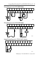
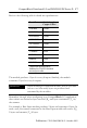
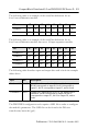
The following table is an example of the word/bit definitions for an
8 in/8 out combination module.
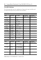
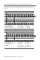
The following table is an example of the word/bit definitions for an
8 in/8 out combination module that uses a 16 input expansion module.
The following table describes input and output bits used in both the example
tables above.
The PROFIBUS configuration tools require a GSD file in order to configure
the module’s parameters. The GSD file can be found at the Web site
www.ab.com/networks/gsd/.
Bit 07 06 05 04 03 02 01 00
Produces I7 I6 I5 I4 I3 I2 I1 I0
Consumes O7 O6 O5 O4 O3 O2 O1 O0
Bit 07 06 05 04 03 02 01 00
Produces 0 I7 I6 I5 I4 I3 I2 I1 I0
Produces1 I15 I14 I13 I12 I11 I10 I9 I8
Produces 2 I23 I22 I21 I20 I19 I18 I17 I16
Consumes 0 O7 O6 O5 O4 O3 O2 O1 O0
Byte Bit Description
Produces 0-2 00-07 Input Status bits - when the bit is set (1), the input is on.
Bit 00 corresponds to input I0, bit 01 corresponds to
input I1, bit 02 corresponds to input I2, and so forth.
Consumes 0 00-07 Output bits - when the bit is set (1), the output will be
turned on. Bit 00 corresponds to output O0, bit 01
corresponds to output O1, bit 02 to output O2, and so
forth.