Installation Instructions CompactBlock Distributed I/O on PROFIBUS DP Series D (Cat. No. 1791P-16B0, -0B16P, -8B8P, -4B4P, -8V8P) 1791P CompactBlock™ I/O modules are stand-alone 24V dc Block I/O products that communicate via a PROFIBUS DP link. Each PROFIBUS DP node consists of either one base module or one base module and one expansion module. Any expansion module can be coupled with any base module. CompactBlock 1791P consists of only base modules.
CompactBlock Distributed I/O on PROFIBUS DP Series D Any illustrations, charts, sample programs, and layout examples shown in this publication are intended solely for purposes of example. Since there are many variables and requirements associated with any particular installation, Rockwell Automation does not assume responsibility or liability (to include intellectual property liability) for actual use based upon the examples shown in this publication. Allen-Bradley publication SGI-1.
CompactBlock Distributed I/O on PROFIBUS DP Series D 3 Environment and Enclosure This equipment is intended for use in a Pollution Degree 2 industrial environment, in overvoltage Category II applications (as defined in IEC publication 60664-1), at altitudes up to 2000 meters without derating. This equipment is considered Group 1, Class A industrial equipment according to IEC/CISPR Publication 11.
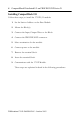
CompactBlock Distributed I/O on PROFIBUS DP Series D Installing CompactBlock I/O Follow these steps, to install the 1791P I/O module: 1. Set the Station Address on the Base Module. 2. Mount the Block(s). 3. Connect the Input/Output Wires to the Block. 4. Connect the PROFIBUS DP connector. 5. Select termination for the module. 6. Connect power to the module. 7. Remove the terminal block. 8. Insert the terminal block. 9. Communicate with the 1791P Module.
CompactBlock Distributed I/O on PROFIBUS DP Series D 5 Preventing Electrostatic Discharge This equipment is sensitive to electrostatic discharge, which can cause internal damage and affect normal operation. Follow these guidelines when you handle this equipment: ATTENTION • Touch a grounded object to discharge potential static. • Wear an approved grounding wriststrap. • Do not touch connectors or pins on component boards. • Do not touch circuit components inside the equipment.
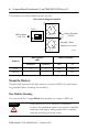
CompactBlock Distributed I/O on PROFIBUS DP Series D The switches are read at module power up only. 4 6 5 2 3 8 7 2 3 4 1 6 5 0 9 Example: Node Address is set at 26 8 7 1’s DIP Switches 100’s Address Rotary Switches (00-99) 1 ON 2 DIP Switches (100-125) 1 100’s 9 0 10’s View when looking into module.
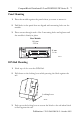
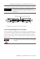
CompactBlock Distributed I/O on PROFIBUS DP Series D 7 Panel Mounting 1. Place the module against the panel where you want to mount it. 2. Drill holes in the panel that are aligned with mounting holes on the module. 3. Place screws through each of the 2 mounting holes and tighten until the module is firmly in place. Base Module 141 mm 5.55 in Module Status Network Status Profibus DP 01 2 34 56 7 Allen-Bradley 01 2 3456 7 41 mm 1.
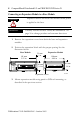
CompactBlock Distributed I/O on PROFIBUS DP Series D Connecting an Expansion Module to a Base Module Expansion blocks should not be installed when power is applied to the base. ATTENTION Carefully read the section “Word/Bit Definitions” on page 18 to change produce and consume data sizes. IMPORTANT 1. Remove the expansion covers from both the base and expansion modules. 2. Position the expansion block with the proper spacing. See the illustration below. Base Module 141 mm 5.
CompactBlock Distributed I/O on PROFIBUS DP Series D 9 4. Plug the expansion cable into both the base and expansion modules. IMPORTANT The expansion cable can only be connected to the modules such that the red stripe on the cable is on top as shown below. Red strip must be on top of ribbon cable. Module Status Network Status Profibus DP 012 3456 7 Allen-Bradley 012 3456 7 CompactBlock I/O 1791P-8V8P 8 INPUTS / 8 OUTPUTS - DC POWER 43117 5. Replace the expansion covers on both modules.
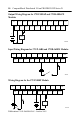
CompactBlock Distributed I/O on PROFIBUS DP Series D Output Wiring Diagram for 1791P-0B16P and 1791D-0B16PX Modules VDC OUT 0 OUT 1 GND OUT 4 OUT 2 OUT 3 OUT 6 OUT 5 VDC OUT 7 OUT 8 GND OUT 10 OUT 9 OUT 12 OUT 11 OUT 14 OUT 13 Not Used OUT 15 + Load 41669 - Input Wiring Diagram for 1791P-16B0 and 1791D-16B0X Modules VDC IN 0 GND IN 4 IN 2 IN 1 IN 3 VDC IN 6 IN 5 IN 7 IN 8 GND IN 10 IN 9 IN 12 IN 11 IN 14 IN 13 Not Used IN 15 + 41671 Wiring Diagram for the 17
CompactBlock Distributed I/O on PROFIBUS DP Series D 11 Wiring Diagram for the 1791P-4B4P Module VDC IN 0 VDC IN 1 GND IN 2 VDC VDC IN 3 VDC GND VDC + + - - OUT 0 GND OUT 1 OUT 2 GND Not Used GND OUT 3 GND Load 42344 Wiring Diagram for the 1791P-8V8P Module VDC IN 0 GND IN 2 IN 1 IN 4 IN 3 IN 6 IN 5 VDC OUT 0 GND IN 7 + - - + OUT 2 OUT 1 OUT 4 OUT 3 Not Used OUT 6 OUT 5 OUT 7 Load 42346 Output Wiring Diagram for 1791D-0V16PX Modules OUT 0 VDC GND +
CompactBlock Distributed I/O on PROFIBUS DP Series D Input Wiring Diagram for 1791D-16V0X Modules IN 0 VDC GND IN 2 IN 1 IN 4 IN 3 IN 6 IN 5 VDC GND IN 7 IN 8 IN 10 IN 9 IN 11 IN 12 IN 13 IN 14 Not Used IN 15 + 41670 Connect the PROFIBUS DP Terminal Connector Refer to the following information when connecting the PROFIBUS DP terminal connector to the 1791P block I/O.
CompactBlock Distributed I/O on PROFIBUS DP Series D 13 1. Connect the PROFIBUS DP female 9-pin D-sub connector to the terminal connector as shown below. Mo Ne Sta dule Statwor tus tus k fibu sD P Pro Pro fibu sD P 0 1 Allen -Bra dley 2 3 4 5 6 7 0 1 2 3 4 Com 8 IN PU TS /8 OU 5 6 7 pac tBlo TP UT S. ck I/O 17 DC 91PPO 8V8P WER 31337-m 2. Connect the terminal connector to the Block. Use the side screws on the terminal connector to fasten it to the Block.
CompactBlock Distributed I/O on PROFIBUS DP Series D Select Termination for the Module The terminator resistor is provided in the connector. Use the DIP switches in the connector to select termination for the module. Refer to the illustration below.
CompactBlock Distributed I/O on PROFIBUS DP Series D 15 Connect Power to the Module To apply power to the 1791P module, refer to the illustration below. Module power connector COM GND +24V Pin Number Name 1 Com (24V dc return) 2 Gnd (Field ground) 3 +24V dc 43108 Remove the Terminal Block WARNING When you connect or disconnect the Removable Terminal Block (RTB) with field side power applied, an electrical arc can occur. This could cause an explosion in hazardous location installations.
CompactBlock Distributed I/O on PROFIBUS DP Series D 2. Lift the terminal block out of the base. Retaining Screw VDC IN0 IN2 GND IN1 IN3 IN4 IN5 Retaining Screw IN6 IN7 VDC IN8 GND IN9 IN1 0 IN 1 IN11 2 IN 14 Not 3 IN Used 15 IN1 43111 Insert the Terminal Block To insert the CompactBlock terminal block: 1. Insert the terminal block by aligning it and pushing it back until it rests against the back of the module. 2.
CompactBlock Distributed I/O on PROFIBUS DP Series D 17 Refer to the following table for baud rate specifications. Baud Rate Cable Length Copper Cable* 9.6KBPS 1000m 19.2KBPS 1000m 45.45KBPS 1000m 93.75KBPS 1000m 187.5KBPS 1000m 500KBPS 400m 1.5MBPS 200m 3MBPS 100m 6MBPS 100m 12MBPS 100m *Specified in PROFIBUS Standard as 22AWG shielded twisted pair cable. The module produces 1 byte for every 8 inputs. Similarly, the module consumes 1 byte for every 8 outputs.
CompactBlock Distributed I/O on PROFIBUS DP Series D Word/Bit Definitions The following table lists the combination of input and output modules and the input and output bytes produced and consumed.
CompactBlock Distributed I/O on PROFIBUS DP Series D 19 The following table is an example of the word/bit definitions for an 8 in/8 out combination module. Bit 07 06 05 04 03 02 01 00 Produces I7 I6 I5 I4 I3 I2 I1 I0 Consumes O7 O6 O5 O4 O3 O2 O1 O0 The following table is an example of the word/bit definitions for an 8 in/8 out combination module that uses a 16 input expansion module.
CompactBlock Distributed I/O on PROFIBUS DP Series D Following are data tables for internal usage between base and expansion modules.
CompactBlock Distributed I/O on PROFIBUS DP Series D 21 Following are data tables on RSLogix500.
CompactBlock Distributed I/O on PROFIBUS DP Series D Maximum Output Data Format (Base Modules -0B16P) Bit Position Word 15 14 13 12 11 10 9 8 7 6 5 4 3 2 1 0 0 O15 O14 O13 O12 O11 O10 O9 O8 O7 O6 O5 O4 O3 O2 O1 O0 1 Reserved Analog Output Data Channel 0 2 Reserved Analog Output Data Channel 1 Base Maximum Input Data Format (Base Modules -8B8P or -8V8P) Bit Position Word 15 14 13 0 12 11 10 9 8 Reserved 7 6 5 4 3 2 1 0 In7 In6 In5 In4 In3 In
CompactBlock Distributed I/O on PROFIBUS DP Series D 23 Maximum Input Data Format (Base Modules -4B4P) Bit Position Word 15 14 13 12 11 0 10 9 8 7 6 5 4 Reserved 1 Reserved Analog Input Data Channel 0 2 Reserved Analog Input Data Channel 1 3 Reserved Analog Input Data Channel 2 4 Reserved 5 3 2 1 0 In3 In2 In1 In0 Reserved RF UF Base Analog Input Data Channel 3 URo1 URo0 ORo1 ORo0 OW3 OW2 OW1 OW0 ORi3 ORi2 ORi1 ORi0 UF Module Unrecoverable Fault RF Module Recovera
CompactBlock Distributed I/O on PROFIBUS DP Series D Troubleshoot with the Indicators The 1791P I/O module has the following indicators: • Module Status indicator - base only • Network Status indicator - base only • I/O Status indicators - base and expansion Module Status Indicator Indication: Status: Off No power Green Module operating correctly Red Hardware or software error Flashing Red Communication failure Flashing Red/Orange Expansion error Network Status Indicator Indication: Status:
CompactBlock Distributed I/O on PROFIBUS DP Series D 25 Specifications Sinking or Sourcing Input Specifications Inputs per block groups of 4 or 8 Off-state Voltage 5V dc maximum On-state Voltage 30V dc @ 40×C maximum 25V dc @ 60×C maximum 10V dc minimum Off-state Current 1.5mA minimum On-state Current 11mA @ 30V dc maximum 2mA @ 10V dc minimum Sinking or Sourcing Output Specifications Outputs per block groups of 4 or 8 On-state Voltage Range 10 - 30V dc On-state Voltage Drop 0.
CompactBlock Distributed I/O on PROFIBUS DP Series D PROFIBUS DP Specifications (continued) Fail Safe Mode Supported1 Station Type Slave FMS Support Not supported Number of nodes 125 maximum Network Length/ Communication rate 9.6KBPS @ 1000m (3280ft) 19.2KBPS @ 1000m (3280ft) 45.45KBPS @ 1000m (3280ft) 93.75KBPS @ 1000m (3280ft) 187.
CompactBlock Distributed I/O on PROFIBUS DP Series D 27 General Specifications (continued) Operating Temperature IEC 60068-2-1 (Test Ad, Operating Cold), IEC 60068-2-2 (Test Bd, Operating Dry Heat), IEC 60068-2-14 (Test Nb, Operating Thermal Shock): 0 to 60°C (32 to 140°F) Field Wiring Tightening Torque 5-7lb-in. (0.5-0.
CompactBlock Distributed I/O on PROFIBUS DP Series D General Specifications (continued) Enclosure Meets IP20 Certifications: (when product is marked) c-UL-us c-UL-us CE4 C-Tick4 UL Listed Industrial Control Equipment, certified for US and Canada UL Listed for Class I, Division 2 Group A,B,C,D Hazardous Locations, certified for U.S. and Canada European Union 89/336/EEC EMC Directive, compliant with: EN 61000-6-4; Industrial Emissions EN 50082-2; Industrial Immunity EN 61326; Meas./Control/Lab.
CompactBlock Distributed I/O on PROFIBUS DP Series D 29 North American Hazardous Location Approval The following information applies when operating this equipment in hazardous locations: Informations sur l’utilisation de cet équipement en environnements dangereux : Products marked “CL I, DIV 2, GP A, B, C, D” are suitable for use in Class I Division 2 Groups A, B, C, D, Hazardous Locations and nonhazardous locations only.
CompactBlock Distributed I/O on PROFIBUS DP Series D Notes: Publication 1791P-IN002B-EN-P - October 2003
CompactBlock Distributed I/O on PROFIBUS DP Series D 31 Notes: Publication 1791P-IN002B-EN-P - October 2003
Rockwell Automation Support Rockwell Automation provides technical information on the web to assist you in using our products. At http://support.rockwellautomation.com, you can find technical manuals, a knowledge base of FAQs, technical and application notes, sample code and links to software service packs, and a MySupport feature that you can customize to make the best use of these tools.