
Safety Modules Owner manual


Rockwell Automation Publication 1791ES-UM001D-EN-P - May 2013 93
Appendix C
Configuration Reference Information
Understand Parameter
Groups
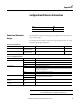
The modules have these parameter groups: general parameters, safety input, test
output, safety output.
See the tables for the settings in each parameter group. All parameters are set by
using the Logix Designer application.
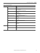
Topic Page
Understand Parameter Groups 93
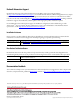
Table 28 - General Parameters
Parameter Name Value Description Default
Safety Output Error Latch Time 0…65,530 ms
(in increments of 10 ms)
Safety output errors are latched for this time. 1000 ms
Safety Input Error Latch Time 0…65,530 ms
(in increments of 10 ms)
Safety input or test output errors are latched for this time. 1000 ms
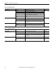
Table 29 - Safety Input Parameters
Parameter Name Value Description
Input Point Operation Type Single Channel Use as single channel.
Dual-channel Equivalent Use as dual-channel. Normal when both channels are ON or OFF.
Dual-channel Complementary Use as dual-channel. Normal when one channel is ON and the other channel is OFF.
Input Point Mode Not Used External input device is not connected.
Safety Test Pulse Use with a contact output device and in combination with a test output. By using this setting, short-
circuits between input signal lines and the power supply (positive side) and short-circuits between
input signal lines can be detected.
Safety A solid-state output safety sensor is connected.
Standard A standard device, such as a reset switch, is connected.
Safety Input Test Source Not Used The test output that is used with the input.
n is dependent on the module catalog number.
Test Output 0 to n
Input Delay Time
Off -> On
0…126 ms (in increments of
6ms)
Filter time for OFF to ON transition
Input Delay Time
On -> Off
0…126 ms (in increments of
6ms)
Filter time for ON to OFF transition
IMPORTANT
When configuring a test output for Pulse Test mode, verify the
corresponding safety input is configured for safety pulse test.