
Safety Modules Owner manual

Rockwell Automation Publication 1791ES-UM001D-EN-P - May 2013 67
Chapter 6
Interpret Module Indicators
Module Indicators
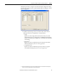
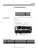
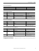
See the figure and tables for information on how to interpret LED module
indicators.
Figure 23 - Module Indicators
Topic Page
Module Indicators 67
Configuration Lock Indicator 69
24V DC Input Power Indicator
Module Status Indicator
Configuration Lock Indicator
24V DC Output Power Indicator
(1791ES-IB8XOBV4 modules only)
I0…I15 - Safety Input Status Indicator
T0…T15 - Test Output Status indicator
00…07 - Safety Output Status Indicator (1791ES-IB8XOBV4 module)
Network Status Indicator
Network
Activity
Indicator
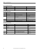
Table 9 - 24V DC Input Power Indicator
State Status Description Recommended Action
Off No power No power is applied. Apply power to this section.
Solid green Normal operation The applied voltage is within specifications. None.
Solid yellow Input power out of specification The input power is out of specification. Check your connectors, wiring, and voltages.