
Safety Modules Owner manual


Rockwell Automation Publication 1791ES-UM001D-EN-P - May 2013 63
Configure the I/O Modules by Using the Logix Designer Application Chapter 5
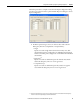
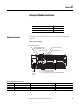
Complete entries on the Test Output dialog box, referring to the figure.
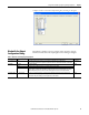
Work with the Output
Configuration Dialog
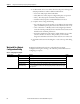
Read this for a guideline on how to configure safety outputs by using the
information in the table and completing the entries referring to the figure.
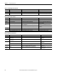
Table 8 - Guidelines for Configuring Safety Outputs
Parameter Name Value Description Default
Point Operation Type Dual The 1791ES module treats the outputs as a pair. It always sets them HI to LO as a matched pair.
Safety logic must set both of these outputs ON or OFF at the same time or the module will declare a channel fault.
Dual-channel
Point Mode Not Used The output is disabled. Not Used
Safety The output point is enabled, and it does not perform a pulse test on the output.
Safety Pulse Test The output point is enabled and performs a pulse test on the output.
When the output is energized, the output pulses LO briefly. The pulse test detects if 24V remains on the output
terminal during this LO pulse due to a short to 24V or if the output is shorted to another output terminal.
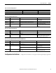
Output Error Latch
Time
0…65,530 ms (in
increments of 10 ms)
The purpose for latching output errors is to make sure that intermittent faults that can only exist for a few
milliseconds are latched long enough to be read by the controller. The amount of time to latch the errors is based
on the RPI, the safety task watchdog, and other application-specific variables.
1000 ms