
Safety Modules Owner manual


Rockwell Automation Publication 1791ES-UM001D-EN-P - May 2013 45
Wiring Examples Chapter 4
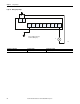
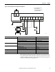
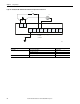
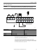
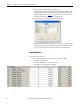
Figure 22 - Dual-load Bipolar Outputs
The example shows wiring and configuration when using the Guard I/O module
with solid state outputs in Dual-channel mode.
Note that all safety outputs of this Guard I/O module are permanently
configured for use as Dual-channel mode only. When used in combination with
the programs of the safety controller, this circuit configuration is Safety Category
4 in accordance with EN 954-1 requirements.
IMPORTANT
In order for the bipolar safety outputs to work correctly, you must connect the devices that are being controlled as
shown in this figure. Connection of devices directly to 24V DC, 0V DC, or Ground is strictly prohibited.
In + In -
FE I0 I1 T0 T1 I2 I3 T2 T3M
PS1
FE
O0
P
O1
M
L- S+
O2
P
O3
M
L- S+
Out
+
Out
-
PS2
K2
K1
K1
K2
M
k2K1
44288
PS1, PS2: User 24V DC power supply
(A single power supply can be used
for both input and output power)
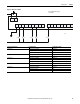
Controller Configuration Parameter Name Configuration Setting
Safety Input 0 Safety Input 0 Channel Mode Test Pulse from Test Output
Safety Input 0 Test Source Test Output 0
Dual-channel Safety Input 0/1 Mode Single Channel
Test Output 0 Test Output 0 Mode Pulse Test Output
Safety Output 0 Safety Output 0 Channel Mode Safety Pulse Test
Safety Output 1 Safety Output 1 Channel Mode Safety Pulse Test