
Safety Modules Owner manual


44 Rockwell Automation Publication 1791ES-UM001D-EN-P - May 2013
Chapter 4 Wiring Examples
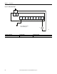
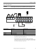
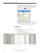
Figure 21 - Guard I/O module with limit switch dual-channel inputs and a manual reset
In + In -
FE I0 I1 T0 T1 I2 I3 T2 T3M
PS1
S1
L1
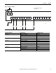
Controller Configuration Parameter Name Configuration Setting
Safety Input 1 Safety Input 1 Channel Mode Standard Input
Safety Input 1 Test Source None
Dual-channel Safety Input 0/1 Mode Single Channel
Test Pulse 0 Test Output 0 Mode 1 Standard Output
44287
PS1: User 24V DC power supply
L1: Lamp
S1: Switch