
Safety Modules Owner manual


Rockwell Automation Publication 1791ES-UM001D-EN-P - May 2013 39
Wiring Examples Chapter 4
Examples of Wiring
Read this section for examples of wiring by application. See catalog number
details for appropriate module.
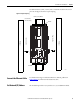
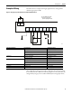
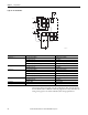
Figure 16 - Emergency Stop Switch Dual-channel Inputs with Manual Reset
This example shows wiring and controller configuration when using the Guard
I/O module. If used in combination with the programs in a safety controller, this
wiring is Safety Category 4 in accordance with EN 954-1 wiring requirements.
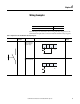
Controller Configuration Parameter Name Configuration Setting
Safety Input 0 Safety Input 0 Channel Mode Test Pulse from Test Output
Safety Input 0 Test Source Test Output 0
Dual-channel Safety Input 0/1 Mode Dual-channel Equivalent
Dual-channel Safety Input 0/1 Discrepancy Time 100 ms (application dependent)
Safety Input 1 Safety Input 1 Channel Mode Test Pulse from Test Output
Safety Input 1 Test Source Test Output 1
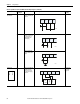
Safety Input 2 Safety Input 2 Channel Mode Used as standard input
Safety Input 2 Test Source Not Used
Dual-channel Safety Input 2/3 Mode Single Channel
Test Output 0 Test Output 0 Mode Pulse Test Output
Test Output 1 Test Output 1 Mode Pulse Test Output
Test Output 2 Test Output 2 Mode Power Supply Output
In + In -
FE I0 I1 T0 T1 I2 I3 T2 T3M
S2
PS1
S1
44281
PS1: User 24V DC power supply
S1: Emergency Stop Switch
(Positive Opening Mechanism)