
Safety Modules Owner manual


38 Rockwell Automation Publication 1791ES-UM001D-EN-P - May 2013
Chapter 4 Wiring Examples
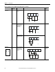
Emergency stop switch
Door monitor
Yes Connect the switches
between I0 and T0, and
I1 and T1
4
No Connect the switches
between T0 and I0 and
I1, noting that T0 is
configured for 24V
power supply.
3
Connect the switches
between 24V DC and I0
and I1.
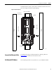
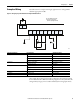
Light Curtain Yes Connect the OSSD1 and
OSSD2 to I0 and I1,
respectively. Connect
the 24V power supply
commons.
3 or 4 based on
light curtain
being used
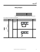
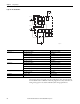
Table 4 - Input Device Connection Methods and Safety Categories (continued)
Connected Device Test Pulse from
Test Output
Connection Schematic Diagram Safety
Category
I0 I1 T0 T1
44277
I0 I1 T0 T1
44278
I0 I1 T0 T1
24V DC
44279
OSSD2
OSSD1
In -I0I1T0T1
24V
DC
COM
OSSD1
OSSD2
44280