User Manual Guard I/O EtherNet/IP Safety Modules Catalog Numbers 1791ES-IB8XOBV4, 1791ES-IB16
Important User Information Solid-state equipment has operational characteristics differing from those of electromechanical equipment. Safety Guidelines for the Application, Installation and Maintenance of Solid State Controls (publication SGI-1.1 available from your local Rockwell Automation sales office or online at http://www.rockwellautomation.com/literature/) describes some important differences between solid-state equipment and hard-wired electromechanical devices.
Summary of Changes Change bars (as shown in this paragraph) show the areas in this manual that are different from previous editions and indicate the addition of revised information. New and Updated Information This table contains the changes made to this revision.
Summary of Changes Notes: 4 Rockwell Automation Publication 1791ES-UM001D-EN-P - May 2013
Table of Contents Preface Studio 5000 Environment . . . . . . . . . . . . . . . . . . . . . . . . . . . . . . . . . . . . . . . . . . 7 Additional Resources . . . . . . . . . . . . . . . . . . . . . . . . . . . . . . . . . . . . . . . . . . . . . . . 7 About the Specifications and Dimensions in This Manual . . . . . . . . . . . . . 8 Terminology. . . . . . . . . . . . . . . . . . . . . . . . . . . . . . . . . . . . . . . . . . . . . . . . . . . . . . . 8 Chapter 1 About the Modules Before You Begin . . .
Table of Contents Chapter 3 Install and Connect Your Modules Install the Module . . . . . . . . . . . . . . . . . . . . . . . . . . . . . . . . . . . . . . . . . . . . . . . . Connect the Ethernet Cable. . . . . . . . . . . . . . . . . . . . . . . . . . . . . . . . . . . . . . . Set Network (IP) Address . . . . . . . . . . . . . . . . . . . . . . . . . . . . . . . . . . . . . . . . . Connect I/O Power and I/O Cables . . . . . . . . . . . . . . . . . . . . . . . . . . . . . . .
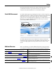
Preface Read and understand this manual before using the described products. Consult your Rockwell Automation representative if you have any questions or comments. This manual describes how to use Guard I/O modules. Studio 5000 Environment The Studio 5000™ Engineering and Design Environment combines engineering and design elements into a common environment. The first element in the Studio 5000 environment is the Logix Designer application.
Preface Resource Description GuardLogix Safety Application Instructions Safety Reference Manual, publication 1756-RM095 Provides reference information describing the GuardLogix Safety Application Instruction Set. Ethernet Design Considerations Reference Manual, publication ENET-RM002 Describes the required media components and how to plan for and install these required components. ODVA Media Planning and Installation Manual, publication 00148-BR00, available from the EtherNet/IP Library at ODVA.
Chapter 1 About the Modules Topic Page Before You Begin 9 Understand Suitability for Use 10 Follow Precautions for Use 10 Precautions to Mount, Wire, and Clean 11 I/O Module Overview 12 About Catalog Numbers 13 Programming Requirements 14 About CIP Safety in EtherNet/IP Safety Architectures 14 Identify Major Parts of the Module 14 This chapter includes important overview information and precautions for use of the Guard I/O modules that implement the EtherNet/IP safety protocol.
Chapter 1 About the Modules Verify that the Guard I/O firmware version is correct prior to commissioning the safety system, noting that firmware information related to safety controllers is available at: http://www.rockwellautomation.com/products/certification/ Understand Suitability for Use Rockwell Automation is not responsible for conformity with any standards, codes, or regulations that apply to the combination of the products in your application or use of the product.
About the Modules Chapter 1 ATTENTION: Use a DC power supply satisfying the following requirements to prevent electric shock: • A DC power supply with double or reinforced insulation, for example, according to IED/EN 60950 or EN 50178 or a transformer according to IEC/EN 61558 • A DC supply satisfies requirement for class 2 circuits or limited voltage/current circuit stated in UL 508 • Use an external power supply that is safety extra-low voltage (SELV) rated • Follow these precautions for safe use.
Chapter 1 About the Modules Follow these instructions when wiring modules. • Do not place communication lines and I/O lines in the same wiring duct or track as high voltage lines. • Wire correctly after confirming the signal names of all terminals. • Follow torquing specifications as indicated in the installation instructions.
About the Modules Chapter 1 The following is a list of features common to Guard I/O modules: • CIP-safety and EtherNet/IP protocol conformance • Safety inputs – Safety devices, such as emergency stop push buttons, gate switches, and safety light curtains, can be connected. – Dual-channel mode evaluates consistency between two input signals (channels), which allows use of the module for Safety Category 3 and 4.
Chapter 1 About the Modules Programming Requirements Use the minimum software versions listed here. Cat. No. Studio 5000 Environment Version(1) RSLogix 5000 Software Version(1) (EtherNet/IP Network) 1791ES-IB16 21 16 1791ES-IB8XOBV4 21 16 (1) This version or later. About CIP Safety in EtherNet/IP Safety Architectures Use Guard I/O modules in EtherNet/IP safety architectures as shown in the figure.
About the Modules Chapter 1 Figure 2 - Major Module Parts Power Connector I/O Connectors LED Status Indicators Network Activity Indicator EtherNet Connector IP Address Switch EtherNet IP Address Label I/O Connectors Rockwell Automation Publication 1791ES-UM001D-EN-P - May 2013 15
Chapter 1 About the Modules Notes: 16 Rockwell Automation Publication 1791ES-UM001D-EN-P - May 2013
Chapter 2 Understand the Operation of Safety Functions Topic Page Self-diagnostic Functions 18 Configuration Lock 18 I/O Status Data 18 Safety Inputs 18 Safety Outputs 27 Controlling Devices 28 Safety Precautions 29 Legislation and Standards 29 EC Directives 31 Read this chapter for information related to the safety functions of the modules. Also included is a brief overview on international standards and directives that you must be familiar with.
Chapter 2 Understand the Operation of Safety Functions Self-diagnostic Functions Self-diagnostics are performed when the power is turned on and periodically during operation. If a fatal internal module error occurs, the red module status (MS) indicator is illuminated, and the safety outputs and input data and status to the network turn off. Configuration Lock After configuration data has been downloaded and verified, the configuration data within the module can be protected.
Understand the Operation of Safety Functions Chapter 2 Using a Test Output with a Safety Input A test output can be used in combination with a safety input for short circuit detection. Configure the test output as a pulse test source and associate it to a specific safety input. The test output can also be used as a power supply to source 24V DC for an external input circuit.
Chapter 2 Understand the Operation of Safety Functions When the external input contact is closed, a test pulse is output from the test output terminal to diagnose the field wiring and input circuitry. By using this function, short-circuits between input signal lines and the power supply (positive side), and short-circuits between input signal lines can be detected.
Understand the Operation of Safety Functions Chapter 2 If an error is detected, safety input data and safety input status turns off.
Chapter 2 Understand the Operation of Safety Functions Set Dual-channel Mode and Discrepancy Time To support redundant channel safety devices, the consistency between signals on two channels can be evaluated. Either equivalent or complementary can be selected. This function monitors the time during which there is a discrepancy between the two channels.
Understand the Operation of Safety Functions Chapter 2 The following table shows the relation between input terminal states and controller input data and status.
Chapter 2 Understand the Operation of Safety Functions Figure 8 - Equivalent, Normal Operation and Fault Detection (not to scale) Normal Operation IN0 ON OFF ON IN1 OFF Discrepancy Time Safety Input 0 ON OFF Remote I/O Data Safety Input 1 ON OFF ON Safety Input Status 0, 1 Fault Detection OFF ON IN0 OFF ON IN1 OFF Discrepancy Time Safety Input 0 ON OFF Remote I/O Data ON Safety Input 1 OFF Safety Input Status 0, 1 ON Fault Detected OFF Dual-channels, Complementary In Complementary mode,
Understand the Operation of Safety Functions Chapter 2 both channel status bits are set low. When configured as a complementary dual channel pair, the data bits for both channels will always be sent to the controller in complementary, or opposite states.
Chapter 2 Understand the Operation of Safety Functions Safety Input Fault Recovery If an error is detected, the safety input data remains in the off state. The procedure for activating the safety input data again is as follows. 1. Remove the cause of the error. 2. Place the safety input (or safety inputs) into the safety state. The safety input status turns on (fault cleared) after the input-error latch time has elapsed. The I/O indicator (red) turns off. The input data can now be controlled.
Understand the Operation of Safety Functions Safety Outputs Chapter 2 Read this section for information about safety outputs. Safety Output with Test Pulse When the safety output is on, the safety output can be test pulsed, as shown in the figure and table. Attribute 1791ES-IB8XOBV4 Pulse width 700 μs Period 600 ms By using this function, short-circuits between output signal lines and the power supply (positive side) and short-circuits between output signal lines can be detected.
Chapter 2 Understand the Operation of Safety Functions Dual-channel Setting When the data of both channels is in the on state, and neither channel has a fault, the outputs are turned on. The status is normal. If a fault is detected on one channel, the safety output data and individual safety output status turn off for both channels.
Understand the Operation of Safety Functions Chapter 2 Table 3 - Controlling Device Requirements Device Emergency stop switches Door interlocking switches, limit switches Safety sensors Relays with forcibly- guided contacts, contactors Other devices Requirement Use approved devices with direct opening mechanisms complying with IEC/EN 60947-5-1. Use approved devices with direct opening mechanisms complying with IEC/EN 60947-5-1 and capable of switching microloads of 24V DC 5 mA.
Chapter 2 Understand the Operation of Safety Functions • EtherNet/IP Conformance • EtherNet/IP Safety Conformance Europe In Europe, the modules are subject to the European Union (EU) Machinery Directive Annex IV, B, Safety Components, items 1 and 2.
Understand the Operation of Safety Functions EC Directives Chapter 2 These products conform to the EMC Directive and Low-voltage Directive. For additional information, refer to the relevant installation instructions. EMC Directive Rockwell Automation devices that comply with EC directives also conform to the related EMC standards so that they can more easily be built into other devices or the overall machine. The actual products have been checked for conformity to EMC standards.
Chapter 2 Understand the Operation of Safety Functions Notes: 32 Rockwell Automation Publication 1791ES-UM001D-EN-P - May 2013
Chapter 3 Install and Connect Your Modules Topic Page Install the Module 34 Connect the Ethernet Cable 35 Set Network (IP) Address 35 Connect I/O Power and I/O Cables 36 ATTENTION: You can configure Test Outputs to be used as standard outputs. You can connect actuators to Test Output points that are expecting a Standard configuration. Test Output points configured as Pulse Test or Power Supply become active whenever you apply input power to the module.
Chapter 3 Install and Connect Your Modules Install the Module IMPORTANT 34 Follow these instructions when installing a module. • Use the module in an environment that is within the general specifications. • Use the module in an enclosure rated IP54 (IEC60529) or higher. • Use DIN rail that is 35 mm (1.38 in.) wide to mount the module in the control panel. • Always use an end plate on each end of the module to secure it.
Install and Connect Your Modules Chapter 3 Use DIN rail that is 35 mm (1.38 in.) wide to install the module in the control panel. See the figure that shows required spacing. Figure 14 - Required Spacing 35 mm (1.38 in.) DIN Rail Use horizontal or vertical mounting. End Plate Wiring Duct 15 mm (0.6 in.) Min 15 mm (0.6 in.) Min Wiring Duct End Plate 44407 Connect the Ethernet Cable See the Ethernet Design Considerations Reference Manual, publication ENET-RM002, for information about Ethernet cable.
Chapter 3 Install and Connect Your Modules To set the network address, you can: • adjust the switches on the front of the module. • use a Dynamic Host Configuration Protocol (DHCP) server, such as Rockwell Automation BootP/DHCP Server Utility. • retrieve the IP address from nonvolatile memory. The module reads the switches first to determine if the switches are set to a valid number. You set the network address by adjusting the three switches on the front of the module.
Chapter 4 Wiring Examples Topic Page Examples of Wiring 39 Read this chapter for information about wiring and safety categories. See the tables that show input device connection methods and their safety categories. Table 4 - Input Device Connection Methods and Safety Categories Connected Device Test Pulse from Test Output Connection Reset Switch No Connect the switch between I0 and T0. T0 must be configured as 24V power supply.
Chapter 4 Wiring Examples Table 4 - Input Device Connection Methods and Safety Categories (continued) Connected Device Test Pulse from Test Output Connection Emergency stop switch Door monitor Yes Connect the switches between I0 and T0, and I1 and T1 Schematic Diagram Safety Category 4 I0 I1 T0 T1 44277 No Connect the switches between T0 and I0 and I1, noting that T0 is configured for 24V power supply. 3 I0 I1 T0 T1 44278 Connect the switches between 24V DC and I0 and I1.
Wiring Examples Chapter 4 Read this section for examples of wiring by application. See catalog number details for appropriate module.
Chapter 4 Wiring Examples Figure 17 - Two-hand Monitor S11 I0 I2 I1 I3 IN+ IN- FE T1 S12 T0 T2 T1 T3 T1 + 31803-M E1 Controller Configuration Parameter Name Configuration Setting Safety Input 0 Safety Input 0 Channel Mode Test Pulse from Test Output Safety Input 0 Test Source Test Output 0 Safety Input 1 Safety Input 2 Dual Channel Safety Input 0/1 Mode Dual Channel Complementary Dual Channel Safety Input 0/1 Discrepancy Time 100 ms (application dependent) Safety Input 1 Chan
Wiring Examples Chapter 4 Figure 18 - Mode Select Switch PS1: User 24V DC power supply S1-S5: Switch PS1 In + In - FE I0 I1 T0 T1 I2 I3 T2 T3M I4 I5 T4 T5 I6 I7 T6 T7M 44283 S1 S2 S3 S4 S5 Controller Configuration Parameter Name Configuration Setting Safety Input 0 Safety Input 0 Channel Mode Safety Input Safety Input 0 Test Source None Dual Channel Safety Input 0/1 Mode Single Channel Safety Input 1 Safety Input 1 Channel Mode Safety Input Safety Input 1 Test Sourc
Chapter 4 Wiring Examples Figure 19 - Muting Lamp Output PS1 In + In - FE I0 I1 T0 T1 I2 I3 T2 PS1: User 24V DC power supply L1: External Muting Lamp T3M L1 44284 Controller Configuration Parameter Name Configuration Setting Test Output 3 Test Output 3 Mode Muting Lamp Output 42 Rockwell Automation Publication 1791ES-UM001D-EN-P - May 2013
Wiring Examples Chapter 4 Figure 20 - Limit Switch Dual-channel Inputs and a Manual Reset PS1: User 24V DC power supply S!: Safety Limit Switch (Positive Opening Mechanism) S2: Safety Limited Switch PS1 In + In - FE I0 I1 T0 T1 I2 I3 T2 T3M S1 (N.C.) Close Safety Guard S2 (N.O.
Chapter 4 Wiring Examples Figure 21 - Guard I/O module with limit switch dual-channel inputs and a manual reset S1 L1 PS1 In + In - FE I0 I1 T0 T1 I2 I3 T2 T3M PS1: User 24V DC power supply L1: Lamp S1: Switch 44287 Controller Configuration Safety Input 1 Test Pulse 0 44 Parameter Name Configuration Setting Safety Input 1 Channel Mode Standard Input Safety Input 1 Test Source None Dual-channel Safety Input 0/1 Mode Single Channel Test Output 0 Mode 1 Standard Output Rockwell Au
Wiring Examples Chapter 4 Figure 22 - Dual-load Bipolar Outputs In order for the bipolar safety outputs to work correctly, you must connect the devices that are being controlled as shown in this figure. Connection of devices directly to 24V DC, 0V DC, or Ground is strictly prohibited.
Chapter 4 Wiring Examples Notes: 46 Rockwell Automation Publication 1791ES-UM001D-EN-P - May 2013
Chapter 5 Configure the I/O Modules by Using the Logix Designer Application Topic Page Use Help 47 Add Modules to the I/O Configuration Tree 47 Use the Module Properties and General Dialogs 49 Work with the Safety Dialog 60 Work with the Input Configuration Dialog 62 Work with Test Output Configuration Dialog 62 Work with the Output Configuration Dialog 63 Save and Download the Module Configuration 65 Use Help At the bottom of a dialog box, choose Help for information about how to comp
Chapter 5 Configure the I/O Modules by Using the Logix Designer Application 1. From the I/O Configuration tree, right-click the EtherNet Bridge module, as shown in the figure, and choose New Module. The Select Module dialog box is displayed with a list that includes Safety.
Configure the I/O Modules by Using the Logix Designer Application Chapter 5 2. From the Select Module dialog box, choose the + next to Safety to see a list of safety modules A list of safety modules appears here. 3. From the Select Module dialog box, choose the appropriate module, such as 1791ES-IB16, and OK at the bottom of the dialog box. Use the Module Properties and General Dialogs To use the Module Properties and General dialogs to configure a module, follow these guidelines. 1.
Chapter 5 Configure the I/O Modules by Using the Logix Designer Application c. For Description, if desired, type a description. For a detailed explanation of the safety network number (SNN), see the GuardLogix Controller Systems Safety Reference Manual listed in the Additional Resources on page 7, noting that in most cases, you use the default provided by the Logix Designer application. d. Click Change to see the Module Definition dialog box. e.
Configure the I/O Modules by Using the Logix Designer Application Chapter 5 • Safety-Readback - This selection is not available for input-only safety modules. Selecting Safety-Readback creates both safety and readback tags, with readback indicating the presence of 24V on the output terminal. Input Status Options Choose from these options. IMPORTANT Status data is not SIL 3 data. Do not use status data to directly control a SIL 3 safety output.
Chapter 5 Configure the I/O Modules by Using the Logix Designer Application • Point Status-Muting - A muting status tag for test output T3/T7 with point status for each input and output point • Combined Status-Muting – A single BOOL tag represents an AND of the status bits for all the input points. For example, if any input channel has a fault, this bit goes LO.(1) – A single BOOL tag represents an AND of the status bits for all the output points.
Configure the I/O Modules by Using the Logix Designer Application Chapter 5 . Output Data Options Choose from these options. IMPORTANT The standard outputs on the module must not be used for safety purposes. • None - Selecting None results in an input only connection to the module. Inputs and status are read, but no outputs are written. • Safety - Selecting Safety creates these safety tags and enables these outputs for use in the safety task.
Chapter 5 Configure the I/O Modules by Using the Logix Designer Application • Test - Selecting Test creates these tags and enables the test outputs on the module. These outputs are standard outputs and must not be used for safety purposes. • Combined - Selecting Combined creates these tags and enables all module outputs - safety and test.
Configure the I/O Modules by Using the Logix Designer Application Chapter 5 Values and States of Tags This table shows the values and states of the tags. Table 5 - Values and States of Tags Data Input data Output data Description Safety Input Data SAFETY Indicates the ON/OFF status of each input circuit. · ON: 1 OFF: 0 Combined Safety Input Status SAFETY An AND of the status of all input circuits.
Chapter 5 Configure the I/O Modules by Using the Logix Designer Application Work with the Safety Dialog Read this for information about how to complete entries when you choose the Safety tab. 1. From the Module Properties dialog box, choose the Safety tab to see the Safety dialog box. 2. Configure Requested Packet Interval (RPI) and Configure Connection Reaction Time Limit (CRTL) by following step 3.
Configure the I/O Modules by Using the Logix Designer Application Chapter 5 3. From the Safety dialog box, choose Advanced to see the Advanced Connection Reaction Time Limit Configuration dialog box. We suggest that you keep the Time-out Multiplier and Network Delay Multiplier at their default values of 2 and 200. See GuardLogix Controllers User Manual, listed in the Additional Resources on page 7, for more information about the CRTL. Make sure that input RPI is set to match the need.
Chapter 5 Configure the I/O Modules by Using the Logix Designer Application A connection status tag exists for every connection. Connection Faulted If the RPI and CRTL for the network are set appropriately, then this status tag must always remain HI. Monitor all connection status bits to verify that they are not going LO intermittently due to timeouts.
Configure the I/O Modules by Using the Logix Designer Application Chapter 5 Configuration Signature The configuration signature is created by the Logix Designer application and verified by the safety module. The configuration signature provides SIL 3 integrity of the configuration of a Guard I/O module. • When a GuardLogix controller first connects to an unconfigured Guard I/ O module, the complete configuration is downloaded to the I/O module.
Chapter 5 Configure the I/O Modules by Using the Logix Designer Application See the table that shows typical safety input parameters, referring to Chapter 2 for related information. Work with the Input Configuration Dialog Table 6 - Typical Safety Input Parameters Parameter Name Value Description Input Point Operation Type Single Channel Inputs are treated as single channel. Dual-channel Equivalent Inputs are treated as a dual-channel pair.
Configure the I/O Modules by Using the Logix Designer Application Chapter 5 Follow this procedure to complete entries from the Input Configuration dialog box that you see when, from the top of the Module Properties dialog box, choose Input Configuration. 1. For Point Operation Type, choose one of these values and a value for Discrepancy Time if set to Equivalent or Complementary: • Single Inputs are treated as single channels.
Chapter 5 Configure the I/O Modules by Using the Logix Designer Application 2. For Point Mode, choose one of these values for each point, referring to the Safety Input Parameters table for additional information: • Not Used - Safety input channel is disabled • Safety Pulse Test - Safety input is configured for pulse test operation • Safety - The safety input is used with a safety field device • Standard - Safety input has a standard field device wired to it 3.
Configure the I/O Modules by Using the Logix Designer Application Chapter 5 Complete entries on the Test Output dialog box, referring to the figure. Read this for a guideline on how to configure safety outputs by using the information in the table and completing the entries referring to the figure.
Chapter 5 Configure the I/O Modules by Using the Logix Designer Application Follow this procedure to complete entries from the Output Configuration dialog box. 1. For Point Operation, all safety outputs are Dual mode only. • The Guard I/O module always sets them high or low as a pair. • You must always match the two outputs as a pair in software as well. 2. For Point Mode, select Not Used, Safety, or Safety Pulse Test, referring to the Safety Output Parameters table for additional information. 3.
Configure the I/O Modules by Using the Logix Designer Application Save and Download the Module Configuration Chapter 5 We recommend that after a module is configured you save your work. If after downloading the program the MS and NS LED indicators on the Guard I/O module are not both solid green, this can be due to loss of ownership.
Chapter 5 Configure the I/O Modules by Using the Logix Designer Application Notes: 66 Rockwell Automation Publication 1791ES-UM001D-EN-P - May 2013
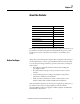
Chapter 6 Interpret Module Indicators Module Indicators Topic Page Module Indicators 67 Configuration Lock Indicator 69 See the figure and tables for information on how to interpret LED module indicators.
Chapter 6 Interpret Module Indicators Table 10 - 24V DC Output Power Indicator State Off Solid green Solid yellow Status No power Normal operation Output power out of specification Description No power is applied. The applied voltage is within specifications. The output power is out of specification. Recommended Action Apply power to this section. None. Check your connectors, wiring, and voltages. Description No power is applied to the power connector. The module is operating normally.
Interpret Module Indicators Chapter 6 Table 13 - Network Activity Indicator State Off Flashing Green Steady Green Status No link established Transmit or receive activity Link established Recommended Action Establish link. None. None. Table 14 - Safety Input Status Indicator State Off Status Safety input off Description The safety input is off or the channel is configured for not used. Solid yellow Solid red Safety input on Fault detected The safety input is on.
Chapter 6 Interpret Module Indicators Notes: 70 Rockwell Automation Publication 1791ES-UM001D-EN-P - May 2013
Appendix A Get Diagnostic Status from Modules by Using Explicit Messaging Topic Page Work with 1791ES-IB8XOBV4 Modules 72 Work with 1791ES-IB16 Modules 77 I/O Data Supported by Each Module 81 I/O Assembly and Reference Data 83 Explicit Messages 88 This appendix provides information about how to use CIP Generic Message instructions (sometimes called explicit messaging) to get diagnostic status information from the modules.
Appendix A Get Diagnostic Status from Modules by Using Explicit Messaging Another choice is to obtain overall status implicitly from the Module Definition dialog box by choosing Combined Status from the Input Status pull-down menu. If the Combined Status changes, use explicit messaging to obtain the point level status. Work with 1791ES-IB8XOBV4 Modules 72 To work with 1791ES-IB8XOBV4 modules, follow this procedure. 1.
Get Diagnostic Status from Modules by Using Explicit Messaging Appendix A This creates a two-byte input assembly, as shown for the 1791ESIB8XOBV4 module. 2. Use the CombinedInputStatus and CombinedOutputStatus bits to detect if one or more of the I/O points on the module have a fault. • If any input or output status bit goes to a value of 0 (0=error, 1=no error), use the InputStatus and OutputStatus bits to condition your msg rungs as follows.
Appendix A Get Diagnostic Status from Modules by Using Explicit Messaging Reference the figures below that show the MSG instruction parameters for reading Instance 852 from the 1791ES-IB8XOBV4 module. Instance 852 (354 Hex) is 5 bytes in length, so the Destination Tag MSGdata must be at least 5 bytes in length to hold this data. The size is DINT[2] or 8 bytes. See the figure that shows the layout of Instance 852 (354 Hex).
Get Diagnostic Status from Modules by Using Explicit Messaging Appendix A From the top of the Message Configuration dialog box, choose the Communication tab. This dialog box requires the path to the module. Click Browse to browse to the module that the MSG will read. From the top of the Message Configuration dialog box, choose Tag to see this dialog box.
Appendix A Get Diagnostic Status from Modules by Using Explicit Messaging When the explicit message reads the data from the 1791ES-IB8XOBV4 module, the data appears in the MSGdata tags as shown. The first 32 bits of the instance are in MSGdata[0].0…31, and the final 8 bits are in MSGdata[1].0…7. These 40 bits must be mapped according to Instance 852. An easy method to do this mapping is to create a user defined tag (UDT) for Instance 852. Once complete, it appears as follows.
Get Diagnostic Status from Modules by Using Explicit Messaging Work with 1791ES-IB16 Modules Appendix A To work with 1791ES-IB16 modules, follow this procedure. 1. In the Module Definition dialog box, from the Input Status pull-down menu, choose Combined Status. This creates a three-byte input assembly, as shown, for the 1791ES-IB16 module.
Appendix A Get Diagnostic Status from Modules by Using Explicit Messaging 2. Use the CombinedInputStatus bit to detect if one or more of the I/O points on the module have a fault. • If any input status bits go to a value of 0 (0 = bad; 1 = good), use an explicit message to determine which individual data points have faulted. • Note that you can use the second rung to read the status on mode transition and once a fault is detected, continue reading until the fault is corrected.
Get Diagnostic Status from Modules by Using Explicit Messaging Appendix A The layout of Instance 869 (365 Hex) is as follows.
Appendix A Get Diagnostic Status from Modules by Using Explicit Messaging From the top of the Message Configuration dialog box, click Tag to see this dialog box. When the explicit message reads the data from the 1791ES-IB16 module, the data appears in the MSGdata tags as shown.
Get Diagnostic Status from Modules by Using Explicit Messaging Appendix A The first 32 bits of the instance are in IB16MSGdata[0].0…31, and the final 24 bits are in IB16MSGdata[1].0…23. Map these 56 bits according to Instance 869. An easy method to do this mapping is to create a user defined tag (UDT) for Instance 869. Once you complete this, it appears as follows. I/O Data Supported by Each Module See the table that shows a summary of default I/O data by module.
Appendix A Get Diagnostic Status from Modules by Using Explicit Messaging For I/O data, safety connections for up to four items, including one output, can be allocated for the master unit. Also, standard connections for up to two items can be allocated for the master unit.
Get Diagnostic Status from Modules by Using Explicit Messaging Appendix A See the tables for I/O assembly and reference data. The bits in the tag definitions of the Logix Designer application are different than those shown in the following section. The following defines the name associations for clarification with the programming software.
Appendix A Get Diagnostic Status from Modules by Using Explicit Messaging Table 21 - Input Data (continued) Instance Hex (Decimal) Module Connection Type Byte Bit 7 225 (549) 1791ESIB16 Safety and Standard 0 Bit 6 Bit 5 Bit 4 Bit 3 Bit 2 Bit 1 Bit 0 Safety Input Safety Input Safety 7 6 Input 5 Safety Input 4 Safety Input 3 Safety Input 2 Safety Input 1 Safety Input 0 1 Safety Input Safety Input Safety 15 14 Input 13 Safety Input 12 Safety Input 11 Safety Input 10 Safety Input 9
Get Diagnostic Status from Modules by Using Explicit Messaging Appendix A Table 21 - Input Data (continued) Instance Hex (Decimal) Module Connection Type Byte Bit 7 344 (836) 1791ESIB8XOBV4 Safety and Standard 0 354 (852) 364 (868) 1791ESIB8XOBV4 1791ESIB8XOBV4 Safety and Standard Safety and Standard Bit 6 Bit 5 Bit 4 Bit 3 Bit 2 Bit 1 Bit 0 Safety Input Safety Input Safety 7 6 Input 5 Safety Input 4 Safety Input 3 Safety Input 2 Safety Input 1 Safety Input 0 1 Safety Input Sa
Appendix A Get Diagnostic Status from Modules by Using Explicit Messaging Table 21 - Input Data (continued) Instance Hex (Decimal) Module Connection Type Byte Bit 7 365 (869) 1791ESIB16 Safety and Standard 0 374 (884) 385 (901) 394 (916) 86 1791ESIB8XOBV4 1791ESIB16 1791ESIB8XOBV4 Safety and Standard Standard Only Standard Only Bit 6 Bit 5 Bit 4 Bit 3 Bit 2 Bit 1 Bit 0 Safety Input Safety Input Safety 7 6 Input 5 Safety Input 4 Safety Input 3 Safety Input 2 Safety Input 1 Sa
Get Diagnostic Status from Modules by Using Explicit Messaging Appendix A Table 21 - Input Data (continued) Instance Hex (Decimal) Module Connection Type Byte Bit 7 Bit 6 Bit 5 Bit 4 Bit 3 Bit 2 Bit 1 Bit 0 3A4 (932) 1791ESIB8XOBV4 Standard Only 0 Reserved Reserved Reserved Reserved Reserved Reserved Output Power Error Input Power Error 1 Safety Output 7 Monitor Safety Output 6 Monitor Safety Output 5 Monitor Safety Output 4 Monitor Safety Output 3 Monitor Safety Output 2 Mon
Appendix A Get Diagnostic Status from Modules by Using Explicit Messaging Explicit messaging can also be used to read individual channel status for safety inputs, safety outputs, test outputs, and power status. Communication error settings can also be configured and monitored for test outputs as well.
Get Diagnostic Status from Modules by Using Explicit Messaging Appendix A Table 26 - Setting Hold/Clear for Communications Errors (Test Output) Explicit Message Service Function Command (hex) Service Code Class ID Instance ID Attribute ID Setting for Output State (Hold or Clear) after Communication Error Get Attribute Single Reads whether hold or clear is set as the output state after a communication error for a test output specified by the instance ID.
Appendix A Get Diagnostic Status from Modules by Using Explicit Messaging Notes: 90 Rockwell Automation Publication 1791ES-UM001D-EN-P - May 2013
Appendix B Safety Data This appendix lists calculated values for probability of failure on demand (PFD), probability of failure per hour (PFH), and mean time between failure (MTTF). PFD and PFH calculations comply with IEC61508, edition 2, 2010. Calculated values of probability of failure on demand and probability of failure per hour appear in the Table 27 and must be calculated for the devices within the system to comply with the SIL level required for application.
Appendix B Safety Data Figure 24 - PFD versus Proof Test Interval 1791ES-IB16 Figure 25 - PFD versus Proof Test Interval 1791ES-IB8XOBV4 Table 27 - Calculated Values for Probability of Failure on Demand (PFD), Probability of Failure per Hour (PFH), and Mean Time To Failure (MTTF) Cat. No. Proof Test Interval Year 1791ES-IB16 1791ES-IB8XOBV4 92 Hour 1 8760 2 17520 PFD (1/hour) PFH (1/hour) Spurious Trip Rate (STR) MTTF (years) 2.06E-06 4.98E-10 3.309E-06 34.48 5.612E-06 20.33 4.
Appendix C Configuration Reference Information Topic Page Understand Parameter Groups 93 The modules have these parameter groups: general parameters, safety input, test output, safety output. Understand Parameter Groups See the tables for the settings in each parameter group. All parameters are set by using the Logix Designer application.
Appendix C Configuration Reference Information Table 30 - Test Output Parameters Parameter Name Value Description Default Test Output Mode Not Used An external device is not connected. Not Used Standard The output is connected to a standard device. Pulse Test A contact output device is connected. Use in combination with a safety input. Power Supply The power supply of a Safety Sensor is connected. The voltage supplied to I/O power (V, G) is output from the test output terminal.
Configuration Reference Information Appendix C Table 32 - Safety and Standard Data Data Input data Output data Description Safety Input Data Safety Indicates the ON/OFF status of each input circuit. • ON: 1 • OFF: 0 Combined Safety Input Status Safety An AND of the status of all input circuits. • All circuits are normal: 1 • An error was detected in one or more input circuits: 0 Individual Safety Input Status Safety Indicates the status of each input circuit.
Appendix C Configuration Reference Information Notes: 96 Rockwell Automation Publication 1791ES-UM001D-EN-P - May 2013
Index A about catalog numbers 13 additional resources 7 administrator, safety 9 architectures, safety 14 B G get point status information 71 glossary 8 Guardmaster product 29 H help button 47 before you begin 9 BootP/DHCP 36 C catalog numbers 13 certification 29 cleaning 12 common terms 8 compliance with EC directive 31 configuration reference information 93 configure the module 47 conformity codes 10 regulations 10 standards 10 controlling devices 28 D dialog General 49 Input Configuration 60 Output
Index PFD See probability of failure on demand. PFH See probability of failure per hour.
Rockwell Automation Support Rockwell Automation provides technical information on the Web to assist you in using its products. At http://www.rockwellautomation.com/support, you can find technical manuals, technical and application notes, sample code and links to software service packs, and a MySupport feature that you can customize to make the best use of these tools. You can also visit our Knowledgebase at http://www.rockwellautomation.