Installation Instructions CompactBlock Guard I/O EtherNet/IP Safety Modules Catalog Numbers 1791ES-IB8XOBV4, 1791ES-IB16 Topic Page Important User Information 2 North American Hazardous Location Approval 3 Environment and Enclosure 4 Preventing Electrostatic Discharge 5 Before You Begin 6 Observing Precautions for Correct Use 7 Installing the Module 7 Setting Network Address 8 Mounting the Module 9 Module Identification and Dimensions 10 Wiring the Module 11 Working with Connectors
CompactBlock Guard I/O EtherNet/IP Safety Modules Important User Information Solid state equipment has operational characteristics differing from those of electromechanical equipment. Safety Guidelines for the Application, Installation and Maintenance of Solid State Controls (Publication SGI-1.1 available from your local Rockwell Automation sales office or online at http://www.rockwellautomation.
CompactBlock Guard I/O EtherNet/IP Safety Modules 3 North American Hazardous Location Approval The following information applies when operating this equipment in hazardous locations. Informations sur l’utilisation de cet équipement en environnements dangereux. Products marked “CL I, DIV 2, GP A, B, C, D” are suitable for use in Class I Division 2 Groups A, B, C, D, hazardous locations and nonhazardous locations only.
CompactBlock Guard I/O EtherNet/IP Safety Modules Environment and Enclosure ATTENTION This equipment is intended for use in a Pollution Degree 2 industrial environment, in overvoltage Category II applications (as defined in IEC 60664-1), at altitudes up to 2000 m (6562 ft) without derating. This equipment is considered Group 1, Class A industrial equipment according to IEC/CISPR Publication 11.
CompactBlock Guard I/O EtherNet/IP Safety Modules 5 Preventing Electrostatic Discharge ATTENTION This equipment is sensitive to electrostatic discharge, which can cause internal damage and affect normal operation. Follow these guidelines when you handle this equipment: • Touch a grounded object to discharge potential static. • Wear an approved grounding wriststrap. • Do not touch connectors or pins on component boards. • Do not touch circuit components inside the equipment.
CompactBlock Guard I/O EtherNet/IP Safety Modules WARNING ATTENTION If you connect or disconnect the communication cable with power applied to this module or any device on the network, an electrical arc can occur. This could cause an explosion in hazardous location installations. To comply with the CE Low Voltage Directive (LVD), this equipment and all connected I/O must be powered from a safety extra-low voltage (SELV) or protected extra-low voltage (PELV) compliant source.
CompactBlock Guard I/O EtherNet/IP Safety Modules 7 Observing Precautions for Correct Use The following information is related to operating directions. Refer to this information after reading the user manual that covers these modules.
CompactBlock Guard I/O EtherNet/IP Safety Modules Setting Network Address Set network (IP address). The module ships with the rotary switches set to 999 and DHCP enabled. To change the network address, you can: • adjust the switches on the front of the module. • use a Dynamic Host Configuration Protocol (DHCP) server, such as Rockwell Automation BootP/DHCP. • retrieve the IP address from nonvolatile memory. The module reads the switches first to determine if the switches are set to a valid number.
CompactBlock Guard I/O EtherNet/IP Safety Modules 9 When the module is reading the network address set on the switches, the module does not have a host name assigned to it or use any Domain Name System. If the switches are set to an invalid number (such as 000 or a value greater than 254), the module checks to see if DHCP is enabled. If DHCP is enabled, the module asks for an address from a DHCP server. The DHCP server also assigns other transport control protocol (TCP) parameters.
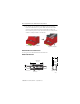
CompactBlock Guard I/O EtherNet/IP Safety Modules • Pry open the two gray latches to lock them in the open position. Hook the module over the top of the DIN rail. Rotate the module downware until it makes full contact with the DIN rail. Snap the latches back into place to secure the module to the rail. Verify that the module is securely attached to the DIN rail. Hook and rotate module on DIN rail. Snap latches into place.
CompactBlock Guard I/O EtherNet/IP Safety Modules 11 Wiring the Module Follow these guidelines when wiring the module: • Do not route communication, input, or output wiring with conduit containing high voltage, referring to Industrial Automation Wiring and Grounding Guidelines, publication 1770-4.1. • Wire correctly after confirming the signal names of all terminals.
CompactBlock Guard I/O EtherNet/IP Safety Modules Observing Precautions for Safe Use Read this for a list of precautions for safe use: • Wire conductors correctly and verify operation of the module before commissioning the system in which the module is incorporated, noting that incorrect wiring may lead to loss of safety function. • Do not apply DC voltages exceeding rated voltages to the module. • Apply properly specified voltages to the module inputs.
CompactBlock Guard I/O EtherNet/IP Safety Modules 13 • Be sure that AC voltage is never applied to the module as module failure will result. ATTENTION Safety state of the module and its data is defined as the off state. Serious injury can occur due to breakdown of safety outputs. Do not connect loads beyond the rated value of the safety outputs. Serious injury can occur due to loss of required safety functions.
CompactBlock Guard I/O EtherNet/IP Safety Modules Controlling Devices - Sample Requirements Device Requirement Allen-Bradley Bulletin Safety Components Emergency stop switch Use approved devices with direct opening mechanism complying with IEC/EN 60947-5-1. Bulletin 800F, 800T Door interlocking switch, limit switch Use approved devices with direct opening mechanism complying with IEC/EN 60947-5-1 and capable of switching microloads of 24V DC 5 mA.
CompactBlock Guard I/O EtherNet/IP Safety Modules 15 Interpret the Status Indicators See the figure and tables for information about how to interpret status indicators.
CompactBlock Guard I/O EtherNet/IP Safety Modules 24V DC Input Power Indicator State Status Description Recommended Action Off No power No power is applied. Apply power to this section. Solid green Normal operation The applied voltage is within specifications. None. Solid yellow Input power out of specification The input power is out of specification. Check your configuration, wiring, and voltages and apply the changes.
CompactBlock Guard I/O EtherNet/IP Safety Modules 17 Module Status Indicator(1) State Status Description Flashing red Recoverable fault or user-initiated firmware update in progress The module has detected a recoverable fault or user-initiated firmware update is in progress. Flashing red and green Device in self test The module is performing its power-cycle diagnostic tests. (1) For recommended action, refer to the user manual that covers these modules.
CompactBlock Guard I/O EtherNet/IP Safety Modules Network Activity Indicator State Status Off No link established Flashing green/off Transmit or receive activity Steady green Link established Safety Input Status Indicator State Status Description Recommended Action Off Safety input off or module being configured The safety input is off or the module is being configured. Turn the safety input on or wait for the module to be configured. Solid yellow Safety input on The safety input is on.
CompactBlock Guard I/O EtherNet/IP Safety Modules 19 Test Output Status Indicator State Status Description Recommended Action Off Test output off or module being configured The test output is off or the module is being configured. Turn the test output on or wait for the module to be configured. Solid yellow Output is on Output is on. None. Solid red Fault detected A fault in the external wiring or input circuit detected. Check field wiring. If no problem found, replace module.
CompactBlock Guard I/O EtherNet/IP Safety Modules Configuration Lock Indicator(1) State Status Description Recommended Action Off No configuration Invalid configuration data. None Solid yellow Locked Valid configuration, locked by a network configuration tool such as RSNetWorx for EtherNet/IP software. None Flashing yellow Not locked Valid configuration, owned by a network configuration tool such as RSNetWorx for EtherNet/IP software. None (1) Not applicable to GuardLogix controllers.
CompactBlock Guard I/O EtherNet/IP Safety Modules 21 Terminal Positions See the figure and table for terminal positions. For wiring diagrams, see the user manual that covers these modules. 18 19 20 21 22 23 24 25 26 27 28 29 30 31 32 33 34 I/O Field Power I/O Field Power 1 = Input +24V DC 2 = Input -24V DC 123456789 3 = Output +24V DC* 4 = Output -24V DC/AC Common* *Applies to 1791ES-IB8XOBV4 module only.
CompactBlock Guard I/O EtherNet/IP Safety Modules Terminal Positions for Numbers 19…34 Number Terminal for 1791ES-IB8XOBV4 Module Terminal for 1791ES-IB16 Module 18 Functional earth Functional earth 19 (1) Safety output 0 /switch +24V DC Safety input 8 20 Safety output 1(1)/switch 24V DC common Safety input 9 21 L-/24V DC common Test output 8 22 S+/24V DC Test output 9 23 Safety output 2(1)/switch +24V DC Safety input 10 24 Safety output 3(1/switch 24V DC common Safety input 11/mu
CompactBlock Guard I/O EtherNet/IP Safety Modules 23 Specifications Guard I/O EtherNet/IP Safety Module - 1791ES-IB8XOBV4, 1791ES-IB16 Attribute Value Safety Input Input types Current sinking Voltage, on-state Input, min 11V DC Current, on-state Input, min 3.3 mA Voltage, off-state input, max 5V DC Current, off-state, max 1.3 mA IEC 61131-2 (input type) Type 3 Pulse Test Output Output type Current sourcing Pulse test output current 0.
CompactBlock Guard I/O EtherNet/IP Safety Modules Guard I/O EtherNet/IP Safety Module - 1791ES-IB8XOBV4, 1791ES-IB16 Attribute Value Safety Output Output types Current sourcing/current sinking - bipolar pair Output current rating 2 A max per point 8 A total module @ 40 °C (104 °F) (see temperature versus current derating) 6 A total module @ 60 °C (140 °F) On-state voltage drop +/- 0.6V Leakage current +/- 1.0 mA(1) Internal resistance from P to M terminal 3.
CompactBlock Guard I/O EtherNet/IP Safety Modules 25 General Attribute Value Isolation voltage 1791ES-IB16 - 50V (continuous), Basic Insulation Type tested at 800VDC for 60 s between input channels and network 1791ES-IB8XOBV4 - 50V (continuous), Basic Insulation Type tested at 800V DC for 60 s between input and output channels and between I/O and network Product temperature versus current derating (for 1791ES-IB8XOBV4 module only) 8A 7A 6A 44199 -20 °C (-4 °F) 40 °C 50 °C 60 °C (104° F) (122 °F) (14
CompactBlock Guard I/O EtherNet/IP Safety Modules Environmental Specifications Attribute Value Temperature, operating IEC 60068-2-1 (Test Ad, Operating Cold), IEC 60068-2-2 (Test Bd, Operating Dry Heat), IEC 60068-2-14 (Test Nb, Operating Thermal Shock): -20…60 °C (-4…140 °F) Temperature, nonoperating IEC 60068-2-1 (Test Ab, Unpackaged Nonoperating Cold), IEC 60068-2-2 (Test Bb, Unpackaged Nonoperating Dry Heat), IEC 60068-2-14 (Test Na, Unpackaged Nonoperating Thermal Shock): -40…85 °C (-40…185 °F)
CompactBlock Guard I/O EtherNet/IP Safety Modules 27 Environmental Specifications Attribute Value Surge transient immunity IEC 61000-4-5: ±1 kV line-line (DM) and ±2 kV line-earth (CM) on power ports ±1 kV line-line (DM) and ±2 kV line-earth (CM) on signal ports ±2 kV line-earth (CM) on communication ports Reaction Time Input reaction time, max 16.2 ms + set values of ON/OFF delays Output reaction time, max 6.2 ms + (20 ms) relay response time (1791ES-IB8XOBV4 module only) Signal Sequence Typ.
Certifications Certification Value Certifications c-UL-us (when product is UL Listed Industrial Control Equipment, certified for US and Canada. See UL File E65584. UL Listed for Class I, Division 2 Group A,B,C,D Hazardous Locations, certified for U.S. and Canada. See UL File E194810. marked)(1) CE European Union 2004/108/EC EMC Directive, compliant with: EN 61326-1; Meas./Control/Lab.