
Safety Module Manual

CompactBlock Guard I/O DeviceNet Safety Modules 9
Publication
1791DS-IN002C-EN-P - April 2009
Wiring the Module
Follow these guidelines when wiring the module:
• Do not route communication, input, or output wiring with conduit
containing high voltage, referring to Industrial Automation Wiring
and Grounding Guidelines, publication 1770-4.1
.
• Wire correctly after confirming the signal names of all terminals.
• Note that stranded wire should be processed with insulation-covered
ferrule (DIN 46228-4 standard compatible-type) at its ends before
using for connection.
• Tighten screws for communication and I/O connectors correctly at
0.25…0.3 N•m (2.21…2.66 lb•in).
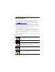
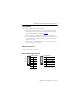
Working with Connectors
See the figure that shows connectors.
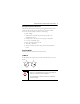
Power and DeviceNet Connectors
DeviceNet Configuration
Color Signal
Red V+
White CAN_H
-Drain
Blue CAN-L
Black V-
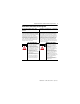
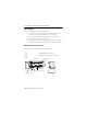
Power Configuration
Pin Signal
1 Input +24V DC Power
2 Input Power Common
3
Output +24V DC Power
(1)
(1)
NC on 1791DS-IB16 modules.
4
Output Power Common
(1)
44045 44046
1
2
3
4
Red
White
-
Blue
Black