Installation Instructions CompactBlock Guard I/O DeviceNet Safety Modules Catalog Numbers 1791DS-IB8XOBV4, 1791DS-IB16 Topic Page Important User Information 2 North American Hazardous Location Approval 3 Environment and Enclosure 4 Preventing Electrostatic Discharge 5 Before You Begin 6 Observing Precautions for Correct Use 7 Install the Module 7 Set MAC ID 7 Mount the Module 8 Module Identification and Dimensions 8 Wiring the Module 9 Working with Connectors 9 Observing Precauti
CompactBlock Guard I/O DeviceNet Safety Modules Important User Information Solid state equipment has operational characteristics differing from those of electromechanical equipment. Safety Guidelines for the Application, Installation and Maintenance of Solid State Controls (Publication SGI-1.1 available from your local Rockwell Automation sales office or online at http://www.rockwellautomation.
CompactBlock Guard I/O DeviceNet Safety Modules 3 North American Hazardous Location Approval The following information applies when operating this equipment in hazardous locations. Informations sur l’utilisation de cet équipement en environnements dangereux. Products marked “CL I, DIV 2, GP A, B, C, D” are suitable for use in Class I Division 2 Groups A, B, C, D, hazardous locations and nonhazardous locations only.
CompactBlock Guard I/O DeviceNet Safety Modules Environment and Enclosure ATTENTION This equipment is intended for use in a Pollution Degree 2 industrial environment, in overvoltage Category II applications (as defined in IEC 60664-1), at altitudes up to 2000 m (6562 ft) without derating. This equipment is considered Group 1, Class A industrial equipment according to IEC/CISPR Publication 11.
CompactBlock Guard I/O DeviceNet Safety Modules 5 Preventing Electrostatic Discharge ATTENTION This equipment is sensitive to electrostatic discharge, which can cause internal damage and affect normal operation. Follow these guidelines when you handle this equipment: • Touch a grounded object to discharge potential static. • Wear an approved grounding wriststrap. • Do not touch connectors or pins on component boards. • Do not touch circuit components inside the equipment.
CompactBlock Guard I/O DeviceNet Safety Modules WARNING ATTENTION If you connect or disconnect the communication cable with power applied to this module or any device on the network, an electrical arc can occur. This could cause an explosion in hazardous location installations. To comply with the CE Low Voltage Directive (LVD), this equipment and all connected I/O must be powered from a safety extra-low voltage (SELV) or protected extra-low voltage (PELV) compliant source.
CompactBlock Guard I/O DeviceNet Safety Modules 7 Observing Precautions for Correct Use The following information is related to operating directions. Refer to this information after reading the user manual that covers these modules.
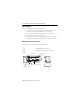
CompactBlock Guard I/O DeviceNet Safety Modules Mount the Module Use these procedures when mounting the module: • Use horizontal or vertical mounting with a DIN rail that is 35 mm (1.4 in.) wide for placing the module in the control panel. • Leave at least 15 mm (0.6 in.) above and below the module for adequate ventilation and room for wiring. • Place all other heat sources an appropriate distance from the module to maintain the specified ambient temperature around the module.
CompactBlock Guard I/O DeviceNet Safety Modules 9 Wiring the Module Follow these guidelines when wiring the module: • Do not route communication, input, or output wiring with conduit containing high voltage, referring to Industrial Automation Wiring and Grounding Guidelines, publication 1770-4.1. • Wire correctly after confirming the signal names of all terminals.
CompactBlock Guard I/O DeviceNet Safety Modules Observing Precautions for Safe Use Read this for a list of precautions for safe use: • Wire conductors correctly and verify operation of the module before commissioning the system in which the module is incorporated, noting that incorrect wiring may lead to loss of safety function. • Do not apply DC voltages exceeding rated voltages to the module. • Apply properly specified voltages to the module inputs.
CompactBlock Guard I/O DeviceNet Safety Modules 11 ATTENTION Safety state of the module and its data is defined as the off state. Serious injury can occur due to breakdown of safety outputs. Do not connect loads beyond the rated value of the safety outputs. Serious injury can occur due to loss of required safety functions. Wire the module properly so that supply voltages or voltages for loads do not touch the safety outputs accidentally or unintentionally.
CompactBlock Guard I/O DeviceNet Safety Modules Interpret the LED Indicators See the tables for information about how to interpret LED indicators. 24V DC Input Power Indicator State Status Description Recommended Action Off No power No power is applied. Apply power to this section. Solid green Normal operation The applied voltage is within specifications. None. Solid yellow Input power out of specification The input power is out of specification.
CompactBlock Guard I/O DeviceNet Safety Modules 13 Module Status Indicator(1) State Status Description Flashing green Module needs commissioning due to missing, incomplete, or incorrect configuration Module is unconfigured. Flashing red Recoverable fault or user-initiated firmware update in progress The module has detected a recoverable fault or user-initiated firmware update is in progress. Flashing red and green Device in self test The module is performing its power-cycle diagnostic tests.
CompactBlock Guard I/O DeviceNet Safety Modules Network Status Indicator(1) State Status Description Flashing red One or more I/O connections in timed-out state or user-initiated firmware update in progress The module detected a recoverable network fault or user-initiated firmware update is in progress. Solid red Critical link failure The module detected an error that prevents it from communicating on the network.
CompactBlock Guard I/O DeviceNet Safety Modules 15 Test Output Status Indicator State Status Description Recommended Action Off Test output off or module being configured The test output is off or the module is being configured. Turn the test output on or wait for the module to be configured. Solid yellow Output is on Output is on. None. Solid red Fault detected A fault in the external wiring or input circuit detected. Check field wiring. If no problem found, replace module.
CompactBlock Guard I/O DeviceNet Safety Modules Configuration Lock Indicator(1) State Status Description Recommended Action Off No configuration Invalid configuration data. None Solid yellow Locked Valid configuration, locked by a network configuration tool, such as RSNetWorx for DeviceNet software. None Flashing yellow Not locked Valid configuration, owned by a network configuration tool, such as RSNetWorx for DeviceNet software. None (1) Not applicable to GuardLogix software.
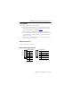
CompactBlock Guard I/O DeviceNet Safety Modules 17 Terminal Positions for Numbers 1…18 Number Terminal for Number Terminal for Number Terminal for 1 Functional Earth 7 Safety Input 3 13 Test Output 5 2 Safety Input 0 8 Test Output 2 14 Safety Input 6 3 Safety Input 1 9 Test Output 3 15 Safety Input 7 4 Test Output 0 10 Safety Input 4 16 Test Output 6 5 Test Output 1 11 Safety Input 5 17 Test Output 7 6 Safety Input 2 12 Test Output 4 18 Functional Earth Terminal Pos
CompactBlock Guard I/O DeviceNet Safety Modules Specifications Guard I/O DeviceNet Safety Module - 1791DS-IB8XOBV4, 1791DS-IB16 Attribute Value Safety Input Input types Current sinking Voltage, on-state input, min 11V DC Current, on-state input, min 3.3 mA Voltage, off-state input, max 5V DC Current, off-state, max 1.3 mA IEC 61131-2 (input type) Type 3 Pulse Test Output Output type Current sourcing Pulse test output current 0.7 A Residual voltage, max 1.
CompactBlock Guard I/O DeviceNet Safety Modules 19 Guard I/O DeviceNet Safety Module - 1791DS-IB8XOBV4, 1791DS-IB16 Attribute Value Leakage current ±1.0 mA(1) Internal resistance from P to M terminal 3.25 kΩ Short circuit detection Yes (short high and low and cross-circuit fault detect) Short circuit protection Electronic Aggregate current of outputs per module 8 A @ 40 °C 6 A @ 60 °C Pilot duty rating 2.
CompactBlock Guard I/O DeviceNet Safety Modules General Specifications Attribute Product temperature versus current derating Value 8A 7A 6A -20 °C 40 °C 50 °C 60 °C 44199 Product Temperature Versus Current Derating (combined current from both input and output supplies) Wiring category(1) 2 - on signal ports 2 - on power ports 2 - on communication ports Wire size 0.34…1.5 mm2 (22…16 AWG) solid or stranded copper wire rated at 75 °C (167 °F) or greater 1.2 mm (3/64 in.
CompactBlock Guard I/O DeviceNet Safety Modules 21 Environmental Specifications Attribute Value Temperature, operating IEC 60068-2-1 (Test Ad, Operating Cold), IEC 60068-2-2 (Test Bd, Operating Dry Heat), IEC 60068-2-14 (Test Nb, Operating Thermal Shock): -20…60 °C (-4…140 °F) Temperature, storage IEC 60068-2-1 (Test Ab, Unpackaged Nonoperating Cold), IEC 60068-2-2 (Test Bb, Unpackaged Nonoperating Dry Heat), IEC 60068-2-14 (Test Na, Unpackaged Nonoperating Thermal Shock): -40…85 °C (-40…185 °F) Relat
CompactBlock Guard I/O DeviceNet Safety Modules Environmental Specifications Attribute Value EFT/B immunity IEC 61000-4-4: ±2 kV at 5 kHz on power ports ±2 kV at 5 kHz on signal ports ±2 kV at 5 kHz on communication ports Surge transient immunity IEC 61000-4-5: ±1 kV line-line (DM) and ±2 kV line-earth (CM) on power ports ±1 kV line-line (DM) and ±2 kV line-earth (CM) on signal ports ±2 kV line-earth (CM) on communication ports Reaction Time Input reaction time, max 16.
CompactBlock Guard I/O DeviceNet Safety Modules 23 Certifications Certification Value Certifications c-UL-us (when product is UL Listed Industrial Control Equipment, certified for US and Canada. See UL File E65584. UL Listed for Class I, Division 2 Group A,B,C,D Hazardous Locations, certified for U.S. and Canada. See UL File E194810. marked)(1) CE European Union 2004/108/EC EMC Directive, compliant with: EN 61326-1; Meas./Control/Lab.
Additional Resources For safe and correct use of the product, read these publications: • DeviceNet Modules in Logix5000 Control Systems User Manual, publication DNET-UM004 • Guard I/O DeviceNet Safety Modules User Manual, publication 1791DS-UM001 You can view or download publications at http://literature.rockwellautomation.com. To order paper copies of technical documentation, contact your local Rockwell Automation distributor or sales representative.