791 Discrete I/O AC and DC Block I/O Input and Output Modules User Manual
Important User Information Because of the variety of uses for the products described in this publication, those responsible for the application and use of this control equipment must satisfy themselves that all necessary steps have been taken to assure that each application and use meets all performance and safety requirements, including any applicable laws, regulations, codes and standards. The illustrations, charts, sample programs and layout examples shown in this guide are intended solely for example.
Summary of Changes Summary of Changes Summary of Changes This release of the publication contains updated information on: revised labels changed fuse specifications which modules do or do not support complementary I/O Manual Organization To help you find new and revised information in this release of the publication, we have included change bars as shown to the right of this paragraph.
Table of Contents Summary of Changes . . . . . . . . . . . . . . . . . . . . . . . . . . . . S 1 Manual Organization . . . . . . . . . . . . . . . . . . . . . . . . . . . . . . . . . S 1 Using This Manual . . . . . . . . . . . . . . . . . . . . . . . . . . . . . . . P 1 Purpose of Manual . . . . . . . . . . . . . . . . . . . . . . . . . . . . . . . . . . . Audience . . . . . . . . . . . . . . . . . . . . . . . . . . . . . . . . . . . . . . . . . . Vocabulary . . . . . . . . . . . . . . . . . . . . .
ii Table of Contents Configuring Your Block I/O for PLC Family Programmable Controllers . . . . . . . . . . . . . . . . . . . . . 4 1 Chapter Objectives . . . . . . . . . . . . . . . . . . . . . . . . . . . . . . . . . . . Setting the Configuration Switches . . . . . . . . . . . . . . . . . . . . . . . . Using Complementary I/O . . . . . . . . . . . . . . . . . . . . . . . . . . . . . . 4 1 4 1 4 9 Troubleshooting . . . . . . . . . . . . . . . . . . . . . . . . . . . . . . . . 5 1 Indicators . . . .
Preface Using This Manual Purpose of Manual This manual shows you how to use your block I/O with an Allen-Bradley programmable controller. It helps you install, program and troubleshoot your module. Audience You must be able to program and operate an Allen-Bradley programmable controller (PLC) to make efficient use of block I/O modules. We assume that you know how to do this in this manual.
Preface Using This Manual About Block I/O Block I/O consists of small, self-contained remote I/O devices complete with power supply, programmable controller interface, input/output connections and signal conditioning circuitry. Table P.A is a list of block I/O modules covered in this publication. Table P.
Chapter 1 Introducing Discrete Block I/O Chapter Objectives In this chapter, you will learn what ac and dc block I/O is, its features, and how it functions. General Description Block I/O modules are small, self-contained remote I/O devices complete with power supply, programmable controller interface, input/output connections and signal conditioning circuitry. Table 1.
Chapter 1 Introducing Block I/O The blocks are compatible with PLC-2, PLC-3, PLC-5/250 and PLC-5 family programmable controllers, and the SLC 5/02 modular controllers. Refer to the table below for information on using block I/O with various Allen-Bradley programmable controllers.
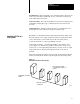
Chapter 1 Introducing Block I/O Terminal Strip - Remote I/O link, power and input/output connections are made to the removable terminal strip for easy connection of wiring, and block replacement if necessary. Switch Assembly - Two switch assemblies are provided for setting the I/O rack number, starting I/O group, communication rate, last chassis, and last state. Status Indicators - Indicators display the status of communication and input/output. Use these indicators to help in troubleshooting.
Chapter 2 I/O Interface and System Design Chapter Objectives In this chapter, you will learn what is compatible with block I/O, how to determine what devices to use, and what fuse to use for outputs. Input Compatibility Block I/O inputs convert ac or dc signals from user devices to the appropriate logic level for use within the processor.
Chapter 2 I/O Interface and System Design DC block input modules are compatible with 1771 series output modules if the off-state leakage current of the module is less than the block module minimum off-state current and the on-state voltage minimum of the dc block input is greater than the supply voltage minus the on-state voltage drop across the 1771 output module.
Chapter 2 I/O Interface and System Design When selecting devices to use with the block I/O inputs, verify that the on–state voltage and currents of the device fall into the on–state region for the block input. Also verify that the off–state current and voltage fall into the off–state region of the block I/O module (Figure 2.1). Figure 2.
Chapter 2 I/O Interface and System Design Example: You want to use an ac 2–wire Bulletin 871C Proximity Switch for an input to a block I/O module.
Chapter 2 I/O Interface and System Design Output Compatibility The block I/O may be used to drive a variety of output devices. Typical output devices compatible with the block I/O outputs include: motor starters solenoids indicators When designing a system, ensure that the block I/O output can supply the necessary surge and continuous current for proper operation. Take care to ensure that the surge and continuous current are not exceeded. Damage to the module could result.
Chapter 2 I/O Interface and System Design Figure 2.6 Simplified Schematic of ac Output Circuit Output Indication LED (logic) System Circuitry L1 Common Opto Isolation 10Ω 178Ω 20-132V ac 0.033µF 75Ω Out RL L2 When sizing output loads, check the documentation supplied with the output device for the surge and continuous current needed to operate the device. Refer to Table 2.A to determine which Allen-Bradley products will directly interface to the outputs.
Chapter 2 I/O Interface and System Design DC Outputs The dc output circuits for block I/O are capable of driving dc loads with a maximum surge current (inrush) of 3A/72 Watts and a maximum holding current of 500mA/12 Watts at 60oC (1A/24 Watts at 30oC). The maximum drive characteristics are shown below (Figure 2.8). Figure 2.8 dc Output Drive Current Surge Current 3A Continuous @ 30oC 1A Continuous @ 60oC 500mA 0 0 50ms Time The drive circuit for dc outputs is shown in Figure 2.9. Figure 2.
Chapter 2 I/O Interface and System Design Relay Output The relay outputs on block I/O modules are electro-mechanical outputs and do not require specific compatibility with the load device as to current sinking or sourcing. Figure 2.10 Simplified Schematic of Relay Output Circuit Input/Output Indication LED (logic) +5V 100Ω 1kΩ 0.033µF System Circuitry L1 Common 20-132V ac L2 Output RL Fusing 12477-I The 16- and 32-point ac and dc block I/O modules are internally fused to protect the module.
Chapter 2 I/O Interface and System Design Table 2.
Chapter 3 Installing Block I/O Chapter Objectives In this chapter, you will learn how to mount the block, connect the input and output wiring to the block, add surge suppression (if required), connect remote I/O wiring, terminate the remote I/O link, and select remote I/O link speed.
Chapter 3 Installing Block I/O When using and PLC 5/20 PLC 5/25 Maximum Capacity 12 blocks with 82 ohm or 150 ohm terminator 16 blocks with 150 ohm terminator, 28 blocks with 82 ohm terminator and extended node addressing 16 blocks/channel, 28 blocks per processor with 150 ohm terminator PLC 5/30 28 blocks/channel, blocks/channel 28 blocks per processor with 82 ohm terminator and extended node addressing 16 blocks/channel, 60 blocks per processor with 150 ohm terminator PLC 5/40 32 blocks/channel,
Chapter 3 Installing Block I/O When using and 16 blocks/channel, 32 blocks/scanner, (128 blocks with 4 scanners) with 150 ohm terminator and extended node addressing PLC 5/250 requires a 5150 RS remote scanner PLC 5 family f il (continued) ( ti d) PLC 5 S C / or SLC 5/03 S C / SLC 5/02 Controllers Baud Rate Used Maximum Capacity 32 blocks/channel, 32 blocks/scanner, (128 blocks with 4 scanners) with 82 ohm terminator and extended node addressing S Remote I/O /O Scanner S 1747 SN Module 16 block
Chapter 3 Installing Block I/O Figure 3.2 Mounting on a DIN Rail 1. Hook top of slot over DIN rail. 2. While pressing block against rail, pull down on locking lever. 3. When block is flush against rail, push up on locking lever(s) to secure block to rail. DIN Rail A B Pt. No. 199 DR1 46277 3 EN 50022 (35 x 7.
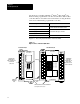
Chapter 3 Installing Block I/O Figure 3.4 Terminal Block Pin Numbering 32 point Block I/O Module 16 point Block I/O Module Refer to the table below for the Figure and page number of the wiring for each block I/O module. Catalog Number Wiring Connections Catalog Number Wiring Connections Catalog Number Wiring Connections 1791 16A0 Figure 3.5, page 3 6 1791 16AC Figure 3.11, page 3 14 1791 8BR Figure 3.17, page 3 23 1791 0A16 Figure 3.6, page 3 7 1791 24A8 Figure 3.
Chapter 3 Installing Block I/O Figure 3.
Chapter 3 Installing Block I/O Figure 3.
Chapter 3 Installing Block I/O Figure 3.7 Input/Output Wiring Connections for the 1791 8AC Series B 1 PLC and SLC 1 2 GND NOT USED RIO BLU CLR COM in COM in COM in in 00 L2/N in 01 in 02 in 03 L1 L1 in 04 in 05 in 06 30 L1 L2/N N NOT USED SHD L1 out L1 out L1 out L1 L2/N out 00 out 01 out 02 out 03 out 04 out 05 out 06 29 out 07 in 07 30 NOTE: COM in connections are internally connected together. L1 out connections must be externally connected together to accommodate total amperage.
Chapter 3 Installing Block I/O Figure 3.8 Input/Output Wiring Connections for the 1791 8AR Series B 1 PLC and SLC 2 1 GND NOT USED RIO BLU N NOT USED SHD CLR Vac/dc COM in COM in COM in in 00 L2/N in 01 in 02 in 03 L1 in 04 in 05 in 06 30 in 07 30 L2/N L1 L1 L1/+ out Vac/dc out Vac/dc out L2/N/ac/dc out 00 out 01 out 02 out 03 out 04 out 05 out 06 29 out 07 NOTE: COM in connections are internally connected together.
Chapter 3 Installing Block I/O Figure 3.9 Input Wiring Connections for the 1791 32A0 Series B PLC 1 1 2 L1 GND NOT USED NOT USED L2/N in 10 in 00 L1 L1 in 06 in 17 1 SLC 1 1 L1 GND BLU CLR COM 1 COM 1 COM 1 in 13 in 05 L1 in 11 in 03 in 15 NOTE: COM 1 connections are internally connected together. COM 2 connections are internally connected together. COM 3 connections are internally connected together. COM 4 connections are internally connected together.
Chapter 3 Installing Block I/O Connections Power Connections Remote I/O Connections 1791-32A0 Series B Connector/Terminal Designation Description Left Conn. L1 ac hot 1 N ac neutral 3 GND Chassis ground 21 BLU Blue wire - RIO 6 CLR Clear wire - RIO 8 SHD Shield - RIO 7 Right Conn.
Chapter 3 Installing Block I/O Figure 3.
Chapter 3 Installing Block I/O Connections Power P Connections Remote R t I/O Connections 1791-0A32 Series B Connector/Terminal Designation Description Left Conn. L1 ac hot 1 N ac neutral 3 Chassis ground 21 GND BLU Blue wire - RIO 6 CLR Clear wire - RIO 8 SHD Shield - RIO 7 Right Conn.
Chapter 3 Installing Block I/O Figure 3.
Chapter 3 Installing Block I/O Connections Power Connections Remote I/O Connections 1791-16AC Series B Connector/Terminal Designation Description Left Conn. L1 ac hot 1 N ac neutral 3 GND Chassis ground 21 BLU Blue wire - RIO 6 CLR Clear wire - RIO 8 SHD Shield - RIO 7 Right Conn.
Chapter 3 Installing Block I/O Figure 3.
Chapter 3 Installing Block I/O Connections Power Connections Remote I/O Connections 1791-24A8 Series B Connector/Terminal Designation Description Left Conn. L1 ac hot 1 N ac neutral 3 GND Chassis ground 21 BLU Blue wire - RIO 6 CLR Clear wire - RIO 8 SHD Shield - RIO 7 Right Conn.
Chapter 3 Installing Block I/O Figure 3.
Chapter 3 Installing Block I/O Connections Power Connections Remote I/O Connections 1791-24AR Series B Connector/Terminal Designation Description Left Conn. L1 ac hot 1 N ac neutral 3 GND Chassis ground 21 BLU Blue wire - RIO 6 CLR Clear wire - RIO 8 SHD Shield - RIO 7 Right Conn.
Chapter 3 Installing Block I/O Figure 3.
Chapter 3 Installing Block I/O Figure 3.
Chapter 3 Installing Block I/O Figure 3.16 Input/Output Wiring Connections for the 1791 8BC Series B 1 PLC and SLC 1 2 GND NOT USED RIO BLU CLR + 24V dc NOT USED RET in RET in in 00 in 01 in 02 in 03 in 04 in 05 in 06 30 in 07 +24 + 24V dc RET +24 NOT USED SHD RET out Vdc out Vdc out + 24V dc out 00 out 01 out 02 out 03 out 04 out 05 out 06 29 out 07 30 NOTE: RET in connections are internally connected together.
Chapter 3 Installing Block I/O Figure 3.17 Input/Output Wiring Connections for the 1791 8BR Series B 1 PLC and SLC 1 2 GND NOT USED RIO BLU CLR + 24V dc + +24 RET +24 in 00 in 01 in 02 in 03 in 04 in 05 in 06 30 in 07 - NOT USED SHD NOT NOT USED USED Vac/dc out RET Vac/dc in out RET in out 00 - 24V dc L1/+ L2N/ac/dc out 01 out 02 out 03 out 04 out 05 out 06 29 out 07 30 NOTE: RET in connections are internally connected together.
Chapter 3 Installing Block I/O Figure 3.
Chapter 3 Installing Block I/O Connections 1791-32B0 Series B Connector/Terminal Designation Description Left Power P Connections +24 +24V dc Power 1 RET +24 dc Return 3 Chassis ground 21 Remote R t I/O Connections BLU Blue wire - RIO 6 CLR Clear wire - RIO 8 Shield - RIO 7 GND SHD Right I/O Connections Input (G)6 Input (G + 1)7 PLC: in 00 thru 07 SLC: in 00 thru 07 PLC: Input 00 thru 07 SLC: Input 00 thru 07 16, 18, 20, 22, 24, 26, 28, 30 RET 1 dc input return 12, 142 P
Chapter 3 Installing Block I/O Figure 3.
Chapter 3 Installing Block I/O Connections 1791-0B32 Series B Connector/Terminal Designation Description Left Power P Connections +24 +24V dc Power 1 RET +24 dc Return 3 Chassis ground 21 Remote R t I/O Connections BLU Blue wire - RIO 6 CLR Clear wire - RIO 8 Shield - RIO 7 GND SHD Right I/O Connections Output (G)6 Output (G + 1)7 PLC: out 00 thru 07 SLC: out 00 thru 07 PLC: Output 00 thru 07 SLC: Output 00 thru 07 16, 18, 20, 22, 24, 26, 28, 30 Vdc 1 +24V dc output supply
Chapter 3 Installing Block I/O Figure 3.
Chapter 3 Installing Block I/O Connections 1791-16BC Series B Connector/Terminal Designation Description Left Power P Connections +24 +24V dc Power 1 RET +24 dc Return 3 Chassis ground 21 Remote R t I/O Connections BLU Blue wire - RIO 6 CLR Clear wire - RIO 8 Shield - RIO 7 GND SHD Right I/O Connections Input (G)6 Output (G)7 PLC: in 00 thru 07 SLC: in 00 thru 07 PLC: Input 00 thru 07 SLC: Input 00 thru 07 16, 18, 20, 22, 24, 26, 28, 30 RET 1 dc input return 12, 142 PLC:
Chapter 3 Installing Block I/O Figure 3.
Chapter 3 Installing Block I/O Connections 1791-24B8 Series B Connector/Terminal Designation Description Left Conn. Power P Connections +24 +24V dc Power 1 RET +24 dc Return 3 Chassis ground 21 Remote R t I/O Connections BLU Blue wire - RIO 6 CLR Clear wire - RIO 8 Shield - RIO 7 GND SHD Right Conn.
Chapter 3 Installing Block I/O Figure 3.
Chapter 3 Installing Block I/O Connections 1791-24BR Series B Connector/Terminal Designation Description Left Conn. Power P Connections +24 +24V dc Power 1 RET +24 dc Return 3 Chassis ground 21 Remote R t I/O Connections BLU Blue wire - RIO 6 CLR Clear wire - RIO 8 Shield - RIO 7 GND SHD Right Conn.
Chapter 3 Installing Block I/O Termination Resistor A termination resistor must be installed on the last block in a series. Connect the resistor as shown in Figure 3.23. Figure 3.23 Installing the Termination Resistor Connect termination resistor across terminals 6 (BLU) and 8 (CLR). BLU Refer to Table 3.A for proper terminator for your application. CLR SHD Termination Resistor Surge Suppression 10835 I Output modules contain surge suppression circuitry for the block output devices.
Chapter 3 Installing Block I/O Figure 3.24 Connecting Surge Suppression Devices L1 GND NOT USED BLU N NOT USED L2/N L1 SHD CLR COM in COM in COM in in 00 in 01 COM out COM out snubber COM out out 00 out 01 out 02 Load in 02 out 03 in 03 in 04 out 04 out 05 in 05 in 06 out 06 out 07 in 07 12346 I The impedance characteristic is the most important factor in selecting a suppression device; thus no single suppression device can be recommended for every possible load. Table 3.
Chapter 3 Installing Block I/O Remote I/O Link Wiring Blocks must be wired in series as shown in Figure 3.25 or Figure 3.26. Do not attempt to wire any block in parallel. The number of blocks used depends not only on the user requirements but also on the system used. Refer to Table 3.A (page 3-1) for maximum block usage for individual systems. Figure 3.
Chapter 3 Installing Block I/O Figure 3.26 Series Configurations for Block I/O Using the SLC Programmable Controller To 1747 SN Scanner Module 1 2 15 16 Up to 16 blocks with SLC 5/02 or SLC 5/03 Install terminating resistor on last block. Extended Node Capability 10834 I If this is the last remote I/O adapter on the remote I/O link in a PLC system, you must use a terminating resistor to terminate both ends of the remote I/O link (scanner end and last block end).
Chapter 3 Installing Block I/O Compatibility of 1771 I/O Products with Extended Node Numbers Certain products are not compatible with extended node capabilities obtained with the use of 82 ohm terminators. Table 3.D lists those products that are not compatible. Table 3.
Chapter 4 Configuring Your Block I/O for PLC Family Programmable Controllers Chapter Objectives In this chapter, you will learn how to configure your block I/O when used with PLC family programmable controllers.
Chapter 4 Configuring Your Block I/O for PLC Family Programmable Controllers Figure 4.
Chapter 4 Configuring Your Block I/O for PLC Family Programmable Controllers Table 4.
Chapter 4 Configuring Your Block I/O for PLC Family Programmable Controllers 1747 SN Rack Number 1771 SN Rack Number PLC-2 Rack Number PLC-5 Rack Number PLC-5/250 Rack Number PLC-3 Rack Number Rack 51 Rack 52 Rack 53 Rack 54 Rack 55 Rack 56 Rack 57 Rack 60 Rack 61 Rack 62 Rack 63 Rack 64 Rack 65 Rack 66 Rack 67 Rack 70 Rack 71 Rack 72 Rack 73 Rack 74 Rack 75 Rack 76 Not Valid SW1 Switch Position 8 7 6 5 4 3 1 1 1 1 1 1 1 1 1 1 1 1 1 1 1 1 1 1 1 1 1 1 1 0 0 0 0 0 0 0 1 1 1 1 1 1 1 1 1 1 1 1 1 1
Chapter 4 Configuring Your Block I/O for PLC Family Programmable Controllers The SLC 500 controllers communicate with the block I/O using an I/O Scanner module (cat. no. 1747-SN series A). Refer to the user manual for the 1747-SN/A Scanner module for more information. Note: These block I/O modules are not compatible with the 1747-DSN Distributed I/O Scanner module. Each block I/O module uses 2 words of output image table memory and 2 words of input image table memory.
Chapter 4 Configuring Your Block I/O for PLC Family Programmable Controllers Figure 4.3 Input/Output Image Table Usage Example for One Starting I/O Group for 16 Output Modules (cat. no.
Chapter 4 Configuring Your Block I/O for PLC Family Programmable Controllers Figure 4.6 I/O Image Table for One Assigned Rack Number with 32 point Modules 1791 16AC 1791 0B32 1791 32B0 1791 32A0 0 1 2 3 4 5 6 7 Input Image 8 7 10 7 15 17 0 SLC 0 PLC Reserved Reserved Reserved 1 I/O Rack Output Image 8 7 10 7 15 17 Reserved Reserved Reserved Reserved 0 1 2 3 4 5 6 7 0 SLC 0 PLC Reserved Figure 4.7 Input/Output Image Table Usage Example for One Starting I/O Group for 32 Output Modules (cat.
Chapter 4 Configuring Your Block I/O for PLC Family Programmable Controllers Figure 4.8 Input/Output Image Table Usage Example for One Starting I/O Group with 32 Input Modules (cat. no.
Chapter 4 Configuring Your Block I/O for PLC Family Programmable Controllers Using Complementary I/O PLC-2 and PLC-5 family processors support a complementary I/O configuration. Complementary I/O can allow you to maximize memory usage without increasing memory size. Refer to the user’s manual for your processor to see if it supports this type of configuration.
Chapter 4 Configuring Your Block I/O for PLC Family Programmable Controllers Remote rack numbers which can have a complementary rack are rack numbers 01 thru 07 only (Table 4.H). When configured as complementary I/O: PLC-2 can scan racks 01–07 PLC-5/11 can scan rack 03 PLC-5/20, PLC-5/30, PLC-5/40, PLC-5/60 can scan racks 01–07 Table 4.
Chapter 4 Configuring Your Block I/O for PLC Family Programmable Controllers Figure 4.13 Input/Output Image Table Usage Example for One I/O Group for Series B 16 point Output Modules (cat. no. 1791 0A16, 0B16) Complemented by Series B 16 point Input Modules (cat. no.
Chapter 4 Configuring Your Block I/O for PLC Family Programmable Controllers Figure 4.15 Input/Output Image Table Usage Example for One I/O Group for Series B 32 point Output Modules (cat. no. 1791 0A32, 0B32) Complemented by Series B 32 point Input Modules (cat. no.
Chapter 4 Configuring Your Block I/O for PLC Family Programmable Controllers Figure 4.17 Input/Output Image Table Usage Example for One I/O Group for Series B 32 point Output Modules (cat. no. 1791 0A32, 0B32) Complemented by Series B 16 point Input Modules (cat. no.
Chapter 5 Troubleshooting Chapter Objectives In this chapter you will learn about the indicators on the block I/O module, and how to use them to troubleshoot the unit. Indicators Each block I/O module has indicators (Figure 5.1) which provide indication of module status.
Chapter 5 Troubleshooting Table 5.A Troubleshooting Chart Indication Probable Cause Corrective Action Green COMM indicator on Red STATUS indicator off I/O status indicator on/off Normal operation None required Red STATUS indicator on Block failed self test, or a major fault is detected. Cycle power to the block. If problem persists, replace the block. Red STATUS indicator flashing Green COMM indicator off Communication failure - RIO cable off, 100ms between valid frames, 20ms idle time exceeded.
$SSHQGL[ 6SHFLILFDWLRQV )RU 6SHFLILFDWLRQV IRU 5HIHU WR $ % 3DJH $ $ % 3DJH $ $& % 3DJH $ $5 % 3DJH $ $ % 3DJH $ $ % 3DJH $ $& % 3DJH $ $ % 3DJH $ $5 % 3DJH $ % % 3DJH $ % % 3DJH $ %& % 3DJH $ %5 % 3DJH $ % % 3DJH $ % % 3DJH $ %& % 3DJH $ % % 3DJH $ %5 % 3DJH $ $
$SSHQGL[ $ 6SHFLILFDWLRQV $ 6HULHV % 6SHFLILFDWLRQV ,QSXW 6SHFLILFDWLRQV ,QSXWV SHU %ORFN JURXSV RI 1RPLQDO ,QSXW &XUUHQW P$ 1RPLQDO ,QSXW 9ROWDJH 9 DF 2QïVWDWH 9ROWDJH 5DQJH ï 9 DF ï +] 2II VWDWH 9ROWDJH 0D[LPXP 9 2Q VWDWH &XUUHQW 0LQLPXP P$ # 9 +] 2II VWDWH &XUUHQW 0LQLPXP P$ +] ,QSXW ,PSHGDQFH 0D[LPXP .
$SSHQGL[ $ 6SHFLILFDWLRQV $ 6HULHV % 6SHFLILFDWLRQV 2XWSXW 6SHFLILFDWLRQV 2XWSXWV SHU %ORFN JURXSV RI 2XWSXW 9ROWDJH 5DQJH ï 9 DF ï +] 2XWSXW &XUUHQW 5DWLQJ 9HUWLFDO 0WJ +RUL]RQWDO 0WJ P$ # R& P$ # R& P$ # R& P$ # R& 6XUJH &XUUHQW $ IRU PV HDFK UHSHDWDEOH HYHU\ VHF 0LQLPXP 2Q VWDWH &XUUHQW P$ SHU RXWSXW 0D[LPXP 2Q VWDWH 9ROWDJH 'URS 9 SHDN # P$ 2II VWDWH /HDNDJH &XUUHQW PD[LPXP P$ 2XWSXW 6LJQDO 'HOD\ 2II WR RQ 2Q WR RII PV #
$SSHQGL[ $ 6SHFLILFDWLRQV $& 6HULHV % 6SHFLILFDWLRQV ,QSXW 6SHFLILFDWLRQV ,QSXWV SHU %ORFN JURXS RI 1RPLQDO ,QSXW &XUUHQW P$ 1RPLQDO ,QSXW 9ROWDJH 9 DF 2Q VWDWH 9ROWDJH 5DQJH ï 9 DF ï +] 2II VWDWH 9ROWDJH 0D[LPXP 9 2Q VWDWH &XUUHQW 0LQLPXP P$ # 9 +] 2II VWDWH &XUUHQW 0LQLPXP P$ +] ,QSXW ,PSHGDQFH 0D[LPXP .
$SSHQGL[ $ 6SHFLILFDWLRQV $5 6HULHV % 6SHFLILFDWLRQV ,QSXW 6SHFLILFDWLRQV ,QSXWV SHU %ORFN JURXS RI 1RPLQDO ,QSXW &XUUHQW P$ 1RPLQDO ,QSXW 9ROWDJH 9 DF 2Q VWDWH 9ROWDJH 5DQJH ï 9 DF ï +] 2II VWDWH 9ROWDJH 0D[LPXP 9 2Q VWDWH &XUUHQW 0LQLPXP 0D[LPXP P$ # 9 +] P$ # 9 +] 2II VWDWH &XUUHQW 0LQLPXP P$ +] ,QSXW ,PSHGDQFH 0D[LPXP .
$SSHQGL[ $ 6SHFLILFDWLRQV $5 6HULHV % 6SHFLILFDWLRQV *HQHUDO 6SHFLILFDWLRQV ([WHUQDO 3RZHU ,QWHUQDOO\ SURWHFWHG QR H[WHUQDO IXVH UHTXLUHG 9ROWDJH &XUUHQW 'LPHQVLRQV ,QFKHV 0LOOLPHWHUV ï 9 DF ï +] P$ + ; : ; ' + ; : ; ' ,VRODWLRQ 3RZHU VXSSO\ WR 5,2 , 2 *URXS WR *URXS , 2 *URXS WR /RJLF %HWZHHQ RSHQ FRQWDFWV 9 DF 9 DF 9 DF 9 DF LQLWLDO 3RZHU 'LVVLSDWLRQ :DWWV 0D[LPXP 7KHUPDO 'LVVLSDWLRQ 0D[LPXP %78 KU (QYLURQPHQWDO &RQGLWLRQV 2SHUDW
$SSHQGL[ $ 6SHFLILFDWLRQV % 6HULHV % 6SHFLILFDWLRQV ,QSXW 6SHFLILFDWLRQV ,QSXWV SHU %ORFN ï JURXSV RI 2Q VWDWH 9ROWDJH 5DQJH ï 9 GF 2Q VWDWH &XUUHQW 0D[LPXP 0LQLPXP P$ # 9 P$ # 9 2II VWDWH 9ROWDJH 0D[LPXP 9 GF 2II VWDWH &XUUHQW 0LQLPXP P$ ,QSXW ,PSHGDQFH 0D[LPXP .
$SSHQGL[ $ 6SHFLILFDWLRQV % 6HULHV % 6SHFLILFDWLRQV 2XWSXW 6SHFLILFDWLRQV 2XWSXWV SHU %ORFN ï JURXSV RI 2XWSXW 9ROWDJH 5DQJH ï 9 GF 2XWSXW &XUUHQW 5DWLQJ 9HUWLFDO 0WJ +RUL]RQWDO 0WJ P$ # R& $ # R& P$ # R& P$ # R& 6XUJH &XUUHQW $ IRU PV HDFK UHSHDWDEOH HYHU\ VHF 0LQLPXP 2Q VWDWH &XUUHQW P$ SHU RXWSXW 0D[LPXP 2Q VWDWH 9ROWDJH 'URS 9 # UDWHG FXUUHQW 2II VWDWH /HDNDJH &XUUHQW PD[LPXP P$ 2XWSXW 6LJQDO 'HOD\ PV RQ PV RII PD[LPXP *HQHUD
$SSHQGL[ $ 6SHFLILFDWLRQV %& 6HULHV % 6SHFLILFDWLRQV ,QSXW 6SHFLILFDWLRQV ,QSXWV SHU %ORFN ï JURXS RI 2Q VWDWH 9ROWDJH 5DQJH ï 9 GF 2Q VWDWH &XUUHQW 0D[LPXP 0LQLPXP P$ # 9 P$ # 9 2II VWDWH 9ROWDJH 0D[LPXP 9 GF 2II VWDWH &XUUHQW 0LQLPXP P$ ,QSXW ,PSHGDQFH 0D[LPXP .
$SSHQGL[ $ 6SHFLILFDWLRQV %5 6HULHV % 6SHFLILFDWLRQV ,QSXW 6SHFLILFDWLRQV ,QSXWV SHU %ORFN ï JURXS RI 2Q VWDWH 9ROWDJH 5DQJH ï 9 GF 2Q VWDWH &XUUHQW 0D[LPXP 0LQLPXP P$ # 9 P$ # 9 2II VWDWH 9ROWDJH 0D[LPXP 9 GF 2II VWDWH &XUUHQW 0LQLPXP P$ ,QSXW ,PSHGDQFH 0D[LPXP .
$SSHQGL[ $ 6SHFLILFDWLRQV %5 6HULHV % 6SHFLILFDWLRQV *HQHUDO 6SHFLILFDWLRQV ([WHUQDO 3RZHU LQWHUQDOO\ SURWHFWHG QR H[WHUQDO IXVH UHTXLUHG 9ROWDJH &XUUHQW 'LPHQVLRQV ,QFKHV 0LOOLPHWHUV ï 9 GF P$ + ; : ; ' + ; : ; ' ,VRODWLRQ 3RZHU VXSSO\ WR 5,2 , 2 *URXS WR *URXS , 2 *URXS WR /RJLF 9 DF 9 DF 9 DF 3RZHU 'LVVLSDWLRQ :DWWV 0D[LPXP 7KHUPDO 'LVVLSDWLRQ 0D[LPXP %78 KU (QYLURQPHQWDO &RQGLWLRQV 2SHUDWLRQDO 7HPSHUDWXUH 6WRUDJH 7HPSHUDWXUH 5HODWLYH +X
$SSHQGL[ $ 6SHFLILFDWLRQV $ 6SHFLILFDWLRQV ,QSXW 6SHFLILFDWLRQV ,QSXWV SHU %ORFN JURXSV RI 1RPLQDO ,QSXW &XUUHQW P$ 1RPLQDO ,QSXW 9ROWDJH 9 DF 2QïVWDWH 9ROWDJH 5DQJH ï 9 DF ï +] 2II VWDWH 9ROWDJH 0D[LPXP 9 2Q VWDWH &XUUHQW 0LQLPXP 0D[LPXP P$ # 9 +] P$ # 9 +] 2II VWDWH &XUUHQW 0LQLPXP P$ +] ,QSXW ,PSHGDQFH 0D[LPXP .
$SSHQGL[ $ 6SHFLILFDWLRQV $ 6SHFLILFDWLRQV 2XWSXW 6SHFLILFDWLRQV 2XWSXWV SHU %ORFN JURXSV RI 2XWSXW 9ROWDJH 5DQJH ï 9 DF ï +] 2XWSXW &XUUHQW 5DWLQJ 9HUWLFDO 0WJ +RUL]RQWDO 0WJ P$ # R& P$ # R& P$ # R& P$ # R& 6XUJH &XUUHQW $ IRU PV HDFK UHSHDWDEOH HYHU\ VHF 0LQLPXP 2Q VWDWH &XUUHQW P$ SHU RXWSXW 0D[LPXP 2Q VWDWH 9ROWDJH 'URS 9 SHDN # P$ 2II VWDWH /HDNDJH &XUUHQW PD[LPXP P$ 2XWSXW 6LJQDO 'HOD\ 2II WR RQ 2Q WR RII PV # +]
$SSHQGL[ $ 6SHFLILFDWLRQV $& 6SHFLILFDWLRQV ,QSXW 6SHFLILFDWLRQV ,QSXWV SHU %ORFN JURXSV RI 1RPLQDO ,QSXW &XUUHQW P$ 1RPLQDO ,QSXW 9ROWDJH 9 DF 2Q VWDWH 9ROWDJH 5DQJH ï 9 DF ï +] 2II VWDWH 9ROWDJH 0D[LPXP 9 2Q VWDWH &XUUHQW 0LQLPXP 0D[LPXP P$ # 9 +] P$ # 9 +] 2II VWDWH &XUUHQW 0LQLPXP P$ +] ,QSXW ,PSHGDQFH 0D[LPXP .
$SSHQGL[ $ 6SHFLILFDWLRQV $ 6SHFLILFDWLRQV ,QSXW 6SHFLILFDWLRQV ,QSXWV SHU %ORFN JURXSV RI 1RPLQDO ,QSXW &XUUHQW P$ 1RPLQDO ,QSXW 9ROWDJH 9 DF 2Q VWDWH 9ROWDJH 5DQJH ï 9 DF ï +] 2II VWDWH 9ROWDJH 0D[LPXP 9 2Q VWDWH &XUUHQW 0LQLPXP 0D[LPXP P$ # 9 +] P$ # 9 +] 2II VWDWH &XUUHQW 0LQLPXP P$ +] ,QSXW ,PSHGDQFH 0D[LPXP .
$SSHQGL[ $ 6SHFLILFDWLRQV $5 6SHFLILFDWLRQV ,QSXW 6SHFLILFDWLRQV ,QSXWV SHU %ORFN JURXSV RI 1RPLQDO ,QSXW &XUUHQW P$ 1RPLQDO ,QSXW 9ROWDJH 9 DF 2Q VWDWH 9ROWDJH 5DQJH ï 9 DF ï +] 2II VWDWH 9ROWDJH 0D[LPXP 9 2Q VWDWH &XUUHQW 0LQLPXP 0D[LPXP P$ # 9 +] P$ # 9 +] 2II VWDWH &XUUHQW 0LQLPXP P$ +] ,QSXW ,PSHGDQFH 0D[LPXP .
$SSHQGL[ $ 6SHFLILFDWLRQV $5 6SHFLILFDWLRQV *HQHUDO 6SHFLILFDWLRQV ([WHUQDO 3RZHU LQWHUQDOO\ SURWHFWHG QR H[WHUQDO IXVH UHTXLUHG 9ROWDJH &XUUHQW 'LPHQVLRQV ,QFKHV 0LOOLPHWHUV ï 9 DF ï +] P$ + ; : ; ' + ; : ; ' ,VRODWLRQ 3RZHU VXSSO\ WR 5,2 , 2 *URXS WR *URXS , 2 *URXS WR /RJLF %HWZHHQ RSHQ FRQWDFWV 9 DF 9 DF 9 DF 9 DF LQLWLDO 3RZHU 'LVVLSDWLRQ :DWWV 0D[LPXP 7KHUPDO 'LVVLSDWLRQ 0D[LPXP %78 KU (QYLURQPHQWDO &RQGLWLRQV 2SHUDWLRQDO
$SSHQGL[ $ 6SHFLILFDWLRQV % 6SHFLILFDWLRQV ,QSXW 6SHFLILFDWLRQV ,QSXWV SHU %ORFN ï JURXSV RI 2Q VWDWH 9ROWDJH 5DQJH ï 9 GF 2Q VWDWH &XUUHQW 0D[LPXP 0LQLPXP P$ # 9 P$ # 9 2II VWDWH 9ROWDJH 0D[LPXP 9 GF 2II VWDWH &XUUHQW 0LQLPXP P$ ,QSXW ,PSHGDQFH 0D[LPXP .
$SSHQGL[ $ 6SHFLILFDWLRQV % 6SHFLILFDWLRQV 2XWSXW 6SHFLILFDWLRQV 2XWSXWV SHU %ORFN ï JURXSV RI 2XWSXW 9ROWDJH 5DQJH ï 9 GF 2XWSXW &XUUHQW 5DWLQJ 9HUWLFDO 0WJ +RUL]RQWDO 0WJ P$ # R& $ # R& P$ # R& P$ # R& 6XUJH &XUUHQW $ IRU PV HDFK UHSHDWDEOH HYHU\ VHF 0LQLPXP 2Q VWDWH &XUUHQW P$ SHU RXWSXW 0D[LPXP 2Q VWDWH 9ROWDJH 'URS 9 # UDWHG FXUUHQW 2II VWDWH /HDNDJH &XUUHQW PD[LPXP P$ 2XWSXW 6LJQDO 'HOD\ PV RQ PV RII PD[LPXP *HQHUDO 6SHFLIL
$SSHQGL[ $ 6SHFLILFDWLRQV %& 6SHFLILFDWLRQV ,QSXW 6SHFLILFDWLRQV ,QSXWV SHU %ORFN ï JURXSV RI 2Q VWDWH 9ROWDJH 5DQJH ï 9 GF 2Q VWDWH &XUUHQW 0D[LPXP 0LQLPXP P$ # 9 P$ # 9 2II VWDWH 9ROWDJH 0D[LPXP 9 GF 2II VWDWH &XUUHQW 0LQLPXP P$ ,QSXW ,PSHGDQFH 0D[LPXP .
$SSHQGL[ $ 6SHFLILFDWLRQV % 6SHFLILFDWLRQV ,QSXW 6SHFLILFDWLRQV ,QSXWV SHU %ORFN ï JURXSV RI 2Q VWDWH 9ROWDJH 5DQJH ï 9 GF 2Q VWDWH &XUUHQW 0D[LPXP 0LQLPXP P$ # 9 P$ # 9 2II VWDWH 9ROWDJH 0D[LPXP 9 GF 2II VWDWH &XUUHQW 0LQLPXP P$ ,QSXW ,PSHGDQFH 0D[LPXP .
$SSHQGL[ $ 6SHFLILFDWLRQV %5 6SHFLILFDWLRQV ,QSXW 6SHFLILFDWLRQV ,QSXWV SHU %ORFN ï JURXSV RI 2Q VWDWH 9ROWDJH 5DQJH ï 9 GF 2Q VWDWH &XUUHQW 0D[LPXP 0LQLPXP P$ # 9 P$ # 9 2II VWDWH 9ROWDJH 0D[LPXP 9 GF 2II VWDWH &XUUHQW 0LQLPXP P$ ,QSXW ,PSHGDQFH 0D[LPXP .
$SSHQGL[ $ 6SHFLILFDWLRQV %5 6SHFLILFDWLRQV *HQHUDO 6SHFLILFDWLRQV ([WHUQDO 3RZHU LQWHUQDOO\ SURWHFWHG QR H[WHUQDO IXVH UHTXLUHG 9ROWDJH &XUUHQW 'LPHQVLRQV ,QFKHV 0LOOLPHWHUV ï 9 GF P$ + ; : ; ' + ; : ; ' ,VRODWLRQ 3RZHU VXSSO\ WR 5,2 , 2 *URXS WR *URXS , 2 *URXS WR /RJLF 9 DF 9 DF 9 DF 3RZHU 'LVVLSDWLRQ :DWWV 0D[LPXP 7KHUPDO 'LVVLSDWLRQ 0D[LPXP %78 KU (QYLURQPHQWDO &RQGLWLRQV 2SHUDWLRQDO 7HPSHUDWXUH 6WRUDJH 7HPSHUDWXUH 5HODWLYH +XPLGLW\
Index Symbols **Empty**, 3 36 B block compatibility, 1 2 16-point modules, 4 11 32-point modules, 4 12 one assigned rack number 16-point and 32-point modules, 4 12 16-point modules, 4 5 32-point modules, 4 7, 4 11 complementary I/O, 4 10 indicators, location, 5 1 C compatibility, 1 2 ac input modules, 2 1 ac output modules, 2 1 dc input modules, 2 2 dc output modules, 2 1 extended node numbers, 3 38 other Allen-Bradley products, 2 2 input compatibility, 2 1 input devices, typical, 2 1 L LED indicators
I–2 Index surge suppression, 3 34 switch settings, 4 2 complementary I/O, 4 10 complementary rack, 4 4 primary rack, 4 3 T terminal block pin numbering, 3 5 removal, 3 4 termination resistor, 3 34 throughput requirements, 3 38 troubleshooting chart, 5 2 Types of block I/O, 1 1 types of block I/O, P 2 W wiring connections, 3 4 1791-0A16, 3 7 1791-0A32, 1791-0B16, 1791-0B32, 1791-16A0, 1791-16AC, 1791-16B0, 1791-16BC, 1791-24A8, 1791-24AR, 1791-24B8, 1791-24BR, 1791-32A0, 1791-32B0, 1791-8AC, 1791-8AR, 1
Allen Bradley has been helping its customers improve productivity and quality for 90 years. A B designs, manufactures and supports a broad range of control and automation products worldwide. They include logic processors, power and motion control devices, man machine interfaces and sensors. Allen Bradley is a subsidiary of Rockwell International, one of the world's leading technology companies. With major offices worldwide.