
Instruction Manual

Chapter
8
8-1
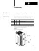
Troubleshooting
In this chapter you will learn about the indicators on the block I/O module,
and how to use them to troubleshoot the unit.
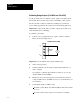
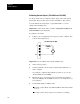
Each block I/O module has indicators (Figure 8.1) which provide
indication of module status. Each module has the following:
Indicator Color Quantity Description
COMM Green 1
Indicates whether communication is occurring between processor or
scanner and the block module
FAULT Red 1 Indicates hardware or software error, and if communication has failed
POWER Green 1 When on, indicates that the module is powered up
Figure 8.1 shows the location of the indicators. Refer to Table 8.A for
status indications reported by the indicators.
Figure 8.1
Indicators
on the Block I/O Module
12404-I
Communication
Indicator
(green)
Fault Status
Indicator
(red)
Power Indicator
(green)
Chapter
Objectives
Module Indicators