
Instruction Manual

Module Calibration
Chapter 7
7-12
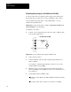
Calibration Example for the 1791N4V2 Block I/O Module
The following example shows you how to calibrate the inputs and outputs
for the 1791-N4V2 block I/O module.
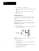
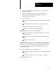
1. For inputs – short all RET and GND together and short V
in
0 thru V
in
3
together. Connect voltage sources and meter between Vin and GND.
For outputs – connect meter and load to each output.
2. Verify normal operation.
3. Set the terminal radix to hexidecimal and set BTW word 0 to C03Fh.
4. Set the voltage source to 0.000V and set the terminal radix to
decimal. Enter the output meter reading in BTW words 1 and 2.
5. Set the terminal radix to hexidecimal and set BTW word 0 to C0BFh.
6. Set BTW word 0 to C07Fh.
7. Set the voltage source to 10.000V and set the terminal radix to
decimal. Enter the output meter reading in BTW words 1 and 2.
8. Set the terminal radix to hexidecimal and set BTW word 0 to C0FFh.
9. Set the terminal radix to decimal and verify module operation.
10. Set the terminal radix to hexidecimal and set BTW word 0 to C8FFh.
11. Return to normal default operation by setting BTW word 0 to 0800h.