
Instruction Manual

Module Calibration
Chapter 7
7-4
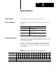
Table 7.E
Discrete
T
ransfer Input Data File
Word/Bit Description
0 Corrected Input Channel 0 Data
1 Corrected Input Channel 1 Data
2 Corrected Input Channel 2 Data
3 Corrected Input Channel 3 Data
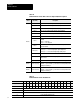
Table 7.F
Discrete
Transfer Input Bit/W
ord Descriptions
Word/Bit Description
0 Corrected Input Data for Channel 0 using most recent calibration data.
1 Corrected Input Data for Channel 1 using most recent calibration data.
2 Corrected Input Data for Channel 2 using most recent calibration data.
3 Corrected Input Data for Channel 3 using most recent calibration data.
Calibrating Voltage Inputs
Use the procedure below to calibrate the voltage inputs on your analog
block I/O module. The procedure can be used for either PLC or SLC
systems.
You can calibrate any single input or output individually or, you can
calibrate them simultaneously.
Important: To allow the module to stabilize, energize the module for at
least 30 minutes before calibrating.
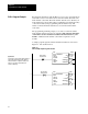
To calibrate your module:
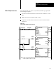
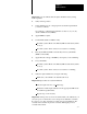
1. Connect your test equipment for the input you want to calibrate. This
is shown in the figure below.
V
IN
I
IN
RET
GND
0-10V
Reference Source
V
V
R