
Instruction Manual

Module Calibration
Chapter 7
7-2
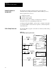
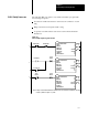
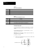
Table 7.B
Calibration
Block Transfer W
rite or Discrete Output Bit/Word Descriptions
Word
Decimal
Bit
(Octal Bit)
Description
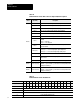
Bit 00 Input select bit. Indicates input channel 0 being calibrated.
Bit 01 Input select bit. Indicates input channel 1 being calibrated.
Bit 02 Input select bit. Indicates input channel 2 being calibrated.
Bit 03 Input select bit. Indicates input channel 3 being calibrated.
Bit 04 Output select bit. Indicates output channel 0 being calibrated.
Bit 05 Output select bit. Indicates output channel 1 being calibrated.
Word 0
Bit 06
High/low bit HL. Indicates whether full scale or zero data point is being
updated:
Bit 06 = 1 - full scale
Bit 06 = 0 - zero data point
Bit 07
Execute Bit. EX. When set (1), starts calibration and updates the
selected channels.
Bit 08 (10)
Input Mode Bit IM.
Bit 08 (10) = 0 - Use for voltage inputs. Input scaling in mV
Bit 08 (10) = 1 - Use for current inputs. Input scaling in µA
Bits 910 (1112) Not used
Bit 11 (13)
EEPROM write bit OK. When set (1), requests the current calibration
data be saved.
Bits 1215 (1417) Calibration mode bits. Set to 1100 to select a calibration sequence.
Word 1 Bits 0015 (0017)
Output Channel 0 Calibration Data - user entered calibration data
when EX = 0 (bit 07 in word 0), scaled and corrected output data when
DN bit (bit 07 in BTR) = 1.
Word 2 Bits 0015 (0017)
Output Channel 1 Calibration Data - user entered calibration data
when EX = 0 (bit 07 in word 0), scaled and corrected output data when
DN bit (bit 07 in BTR) = 1.
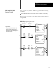
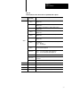
Table 7.C
Calibration
Block Transfer Read Data File
Word/ Octal Bit 17 16 15 14 13 12 11 10 07 06 05 04 03 02 01 00
Word/Decimal Bit 15 14 13 12 11 10 09 08 07 06 05 04 03 02 01 00
0 1 1 0 0 OK IM DN HL O1 O0 I3 I2 I1 I0
1 Corrected Input Channel 0 Data
2 Corrected Input Channel 1 Data
3 Corrected Input Channel 2 Data
4 Corrected Input Channel 3 Data