
Instruction Manual

Chapter
7
7-1
Module Calibration
In this chapter we tell you how to calibrate your module.
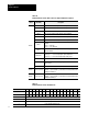
To calibrate your analog module, you will need the following tools and
equipment:
Tool or Equipment Description
Precision Voltage Source
0-10V, 1µV resolution
Precision Multimeter
25mA, 1µA resolution
10V, 1
µV resolution
Programming Terminal
and Interconnect Cable
Programming terminal for A-B family processors
Your analog module is shipped already calibrated from the factory. To
recalibrate the module, it must be able to communicate with the processor
and a programming terminal.
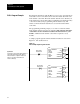
If the processor has block transfer capability, you must enter ladder logic
into the processor memory before calibrating the module. You can then
initiate BTWs to the module, and the processor can read inputs from the
module (BTRs).
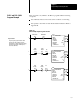
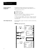
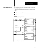
Table 7.A
Calibration
Block Transfer W
rite Data File or Discrete Output Data File
Discrete Octal Bit 17 16 15 14 13 12 11 10 07 06 05 04 03 02 01 00
Discrete Decimal Bit 15 14 13 12 11 10 09 08 07 06 05 04 03 02 01 00
Word 0 1 1 0 0 WR IM EX HL O1 O0 I3 I2 I1 I0
Word 1 Output Channel 0 Calibration Data
Word 2 Output Channel 1 Calibration Data
Chapter
Objective
Tools and Equipment
Calibrating your Module