
Instruction Manual

Chapter 6
Programming Your Analog Module
6-3
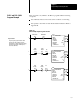
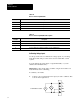
This program is very similar to the PLC-3 program with the following
exceptions:
Use enable bits instead of done bits as the conditions on each rung.
Use separate control files for each block transfer instruction. Refer to
Appendix B.
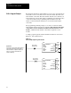
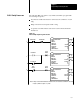
Figure 6.2
PLC5
Family Sample Program Structure
EN
BTR
BLOCK XFER READ
RACK:
GROUP:
MODULE:
CONTROL:
1
0
0
N7:0
DN
DATA FILE:
LENGTH:
CONTINUOUS:
N10:0
5
N
ER
BTR Enable
15
1
EN
BTW
BLOCK XFER WRITE
RACK:
GROUP:
MODULE:
CONTROL:
1
0
0
N7:5
DN
DATA FILE:
LENGTH:
CONTINUOUS:
N10:10
27
N
ER
2
BTW Enable
15
N7:5N7:0
EN
BTW
BLOCK XFER WRITE
RACK:
GROUP:
MODULE:
CONTROL:
1
0
0
N7:10
DN
DATA FILE:
LENGTH:
CONTINUOUS:
N10:10
3
N
ER
BTR
15
15
3
BTW
Enable
Enable
N7:5N7:0
15
N10:0
BTR
15
15
BTW
Enable
Enable
PU
N7:5N7:0
15
N10:0
PU
At
powerup, the program enables a block
transfer read. Then, it initiates one block
transfer write to configure the module (rung 2).
Thereafter
, the program continuously does
block reads and writes.
Program Action
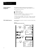
PLC5
and PLC-5/250
Program Example