
Instruction Manual

Analog Block Applications Using
Discrete Transfers
Chapter 5
5-2
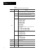
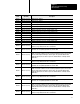
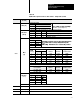
Table 5.A
Input
Image T
able
Word
Bit - Decimal
(Bit - Octal)
Description
Word 0
Bits 00-15
(00-17)
Input data for channel 0.
Word 1
Bits 00-15
(00-17)
Input data for channel 1.
Word 2
Bits 00-15
(00-17)
Input data for channel 2.
Word 3
Bits 00-15
(00-17)
Input data for channel 3.
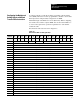
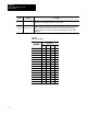
The output image table data format consists of four words. Word 0 is the
configuration word consisting of the output enable bit (OE), module mode,
scaling bit (SM), range select bits, and filter bits. SLC configuration word
is a subset of the PLC except an enable output bit is added; alarms and user
scaling are removed. Words 1 and 2 contain output data. Word 3 is
reserved.
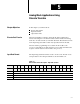
When using the analog block modules with an SLC controller, data is
transferred as discrete data. The data is processed through a 1747-SN
remote I/O scanner module.
The following tables show the word/bit assignments for both discrete input
and output transfer.
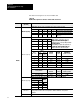
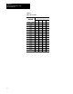
Figure 5.2
Discrete
Data T
ransfer Description - Output T
able 1/2 Rack
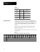
Decimal 15 14 13 12 11 10 09 08 07 06 05 04 03 02 01 00
Octal 17 16 15 14 13 12 11 10 07 06 05 04 03 02 01 00
0 OE Module Mode SM Range Filter
1 Output Channel 0 Data
2 Output Channel 1 Data
3 Not used
Output Data Format