
Instruction Manual

Chapter 4
Analog Block Applications Using
Block Transfers
4-5
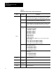
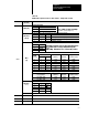
Description
Decimal Bit
(Octal Bit)
Word
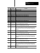
Word 1 Bits 0015 (0017) Output data for channel 0.
Word 2 Bits 0015 (0017) Output data for channel 1.
Word 3 Bits 0015 (0017) Minimum engineering scale factors for output channel 0 data.
Word 4 Bits 0015 (0017) Maximum engineering scale factors for output channel 0 data.
Word 5 Bits 0015 (0017) Minimum engineering scale factors for output channel 1 data.
Word 6 Bits 0015 (0017) Maximum engineering scale factors for output channel 1 data.
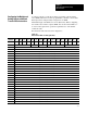
Word 7 Bits 0015 (0017) Minimum engineering scale factors for input channel 0 data.
Word 8 Bits 0015 (0017) Maximum engineering scale factors for input channel 0 data.
Word 9 Bits 0015 (0017) Minimum engineering scale factors for input channel 1 data.
Word 10 Bits 0015 (0017) Maximum engineering scale factors for input channel 1 data.
Word 11 Bits 0015 (0017) Minimum engineering scale factors for input channel 2 data.
Word 12 Bits 0015 (0017) Maximum engineering scale factors for input channel 2 data.
Word 13 Bits 0015 (0017) Minimum engineering scale factors for input channel 3 data.
Word 14 Bits 0015 (0017) Maximum engineering scale factors for input channel 3 data.
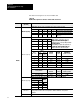
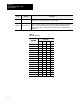
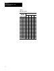
Word 15 Bits 0015 (0017)
Low alarm level for input channel 0. When the input value for this channel is less than the low
value, the corresponding low alarm bit is set in the BTR.
Word 16 Bits 0015 (0017)
High alarm level for input channel 0. When the input value for this channel is greater than the
high value, the corresponding high alarm bit is set in the BTR.
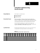
Word 17 Bits 0015 (0017)
Alarm deadband for input channel 0. This field creates a hysteresis effect on the low and high
alarms. For an alarm condition to be removed, the input signal must go above the low alarm
limit or below the high alarm limit by an amount equal to the specified deadband. Alarm
deadband values must be less than or equal to one half the difference of the high and low
alarm values.
Word 18 Bits 0015 (0017)
Low alarm level for input channel 1. When the input value for this channel is less than the low
value, the corresponding low alarm bit is set in the BTR.
Word 19 Bits 0015 (0017)
High alarm level for input channel 1. When the input value for this channel is greater than the
high value, the corresponding high alarm bit is set in the BTR.
Word 20 Bits 0015 (0017)
Alarm deadband for input channel 1. This field creates a hysteresis effect on the low and high
alarms. For an alarm condition to be removed, the input signal must go above the low alarm
limit or below the high alarm limit by an amount equal to the specified deadband. Alarm
deadband values must be less than or equal to one half the difference of the high and low
alarm values.
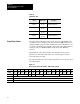
Word 21 Bits 0015 (0017)
Low alarm level for input channel 2. When the input value for this channel is less than the low
value, the corresponding low alarm bit is set in the BTR.
Word 22 Bits 0015 (0017)
High alarm level for input channel 2. When the input value for this channel is greater than the
high value, the corresponding high alarm bit is set in the BTR.
Word 23 Bits 0015 (0017)
Alarm deadband for input channel 2. This field creates a hysteresis effect on the low and high
alarms. For an alarm condition to be removed, the input signal must go above the low alarm
limit or below the high alarm limit by an amount equal to the specified deadband. Alarm
deadband values must be less than or equal to one half the difference of the high and low
alarm values.
Word 24 Bits 0015 (0017)
Low alarm level for input channel 3. When the input value for this channel is less than the low
value, the corresponding low alarm bit is set in the BTR.