
Instruction Manual

Analog Block Applications Using
Block Transfers
Chapter 4
4-4
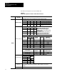
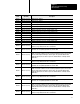
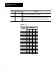
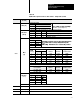
The bit/word descriptions are shown in Table 4.B.
Table 4.B
Bit/Word
Descriptions for the Block T
ransfer W
rite Instruction
Word
Decimal
Bit
(Octal Bit)
Description
Module Mode. Bits 1215 (1417) determine the operation of the block module.
Bit 15 (17) 14 (16) 13 (15) 12 (14)
Bits 1215 (1417)
0 0 0 0 Normal operation with voltage inputs
Bits 1215 (1417)
0 0 0 1 Normal operation with current inputs
1 1 0 0
Calibration operation (refer to
Chapter 7)
Scaler Mode
Bit 11 (13) 10 (12) Mode Binary Counts binary data sent to the
outputsandreturnedfromtheinputsis
0 X binary
outputs and returned from the inputs is
calibrated, but not scaled, providing maximum
possibleresolution
1 0 default
possible resolution.
User Scaling the input and output data are
scaledbythevaluesinwords3thru6for
1 1 user
scaled by the values in words 3 thru 6 for
outputs, and words 7 thru 14 for inputs.
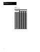
Default Scaling Values are shown below:
Module
Range
Default Default Approximate
Bits 1011 (1213)
Module
Mode
Bit 12 (14)
Bit 09
(11)
Bit 08
(10)
Default
Minimum
Default
Maximum
Approximate
Default Resolution
0 0 0 10000 +10000 14 Bits
0 0 1 5000 +5000 13 Bits
Word0
1 0 1 20000 +20000 14 Bits
Word 0
0 1 0 0000 +10000 13 Bits
0 1 1 0000 +5000 12 Bits
1 1 1 0000 +20000 14 Bits
Default scaling for the output is determined by the catalog number as follows:
Catalog Number
Default
Minimum
Default
Maximum
Approximate
Default Resolution
1791N4V2, NDV 10000 +10000 14 Bits
1791N4C2, NDC 00000 +20000 13 Bits
Range selection bits. Bit 08 selects voltage and bit 09 selects unipolar or bipolar.
Bit
Range
Bits 0809 (1011) 09 (11) 08 (10)
Range
()
0 0 +10V
0 1 +5V
1 0 010
1 1 05
Bits 0407
Alarm Enable bits. Enables input alarm when set (1). Bit 04 corresponds to channel 0, bit 05
corresponds to channel 1, bit 06 corresponds to channel 2 and bit 07 corresponds to
channel 3.
Bits 0003 Digital Filter selection. Default of 0000 selects No Filter. Refer to Table 4.C.