
Instruction Manual

Chapter 4
Analog Block Applications Using
Block Transfers
4-3
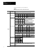
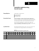
You must configure your block module by performing a block transfer
write (BTW) instruction from the programmable controller to the module.
Each input can be independently configured in one BTW.
Maximum length of the BTW is 27 words (0 thru 26). When configuring
the module, first send the complete BTW. You can shorten the BTW to 3
words for subsequent write operations if parameters for each channel
remain the same.
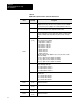
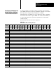
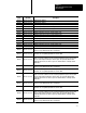
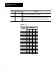
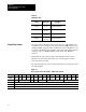
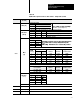
Block transfer write data is shown in Figure 4.2.
Figure 4.2
Block
T
ransfer W
rite for Analog Block I/O
Decimal 15 14 13 12 11 10 09 08 07 06 05 04 03 02 01 00
Octal 17 16 15 14 13 12 11 10 07 06 05 04 03 02 01 00
0 Module Mode Scaling Range Alarm Enable Filter
1 Output Channel 0 Data
2 Output Channel 1 Data
3 Output Channel 0 Minimum Scaling
4 Output Channel 0 Maximum Scaling
5 Output Channel 1 Minimum Scaling
6 Output Channel 1 Maximum Scaling
7 Input Channel 0 Minimum Scaling
8 Input Channel 0 Maximum Scaling
9 Input Channel 1 Minimum Scaling
10 Input Channel 1 Maximum Scaling
11 Input Channel 2 Minimum Scaling
12 Input Channel 2 Maximum Scaling
13 Input Channel 3 Minimum Scaling
14 Input Channel 3 Maximum Scaling
15 Input Channel 0 Low Alarm Level
16 Input Channel 0 High Alarm Level
17 Input Channel 0 Alarm Deadband
18 Input Channel 1 Low Alarm Level
19 Input Channel 1 High Alarm Level
20 Input Channel 1 Alarm Deadband
21 Input Channel 2 Low Alarm Level
22 Input Channel 2 High Alarm Level
23 Input Channel 2 Alarm Deadband
24 Input Channel 3 Low Alarm Level
25 Input Channel 3 High Alarm Level
26 Input Channel 3 Alarm Deadband
Configuring the Module and
Setting Outputs with Block
T
ransfer W
rite Instructions