
Instruction Manual

Chapter
4
4-1
Analog Block Applications Using
Block Transfers
In this chapter, you will read about:
reading data and status from the module
block transfer read data format
configuring the module and setting outputs with block transfer
write instructions
Block transfer instructions are used when the analog block is used with
PLC programmable controllers with block transfer capability. Block
transfer read (BTR) programming moves status and data from the module
to the processor’s data table in one I/O scan. The processor user program
initiates the request to transfer data from the module to the processor.
The transferred words contain module status, channel status and input data
from the module. The maximum BTR data file length required is five
words (0 thru 4).
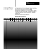
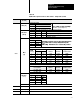
The block transfer read data format consists of input data and module
status. Word 0 contains the power up bit (PU), the bad configuration bit
(BC), out of range bit (OR), status code, high alarm and low alarm bits.
Words 1 through 4 contain input channel data.
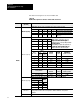
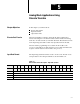
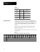
Complete configuration data and bit/word descriptions are shown in
Figure 4.1 and Table 4.A.
Figure 4.1
Block
T
ransfer Read for Analog Blocks using PLC Controllers
Decimal 15 14 13 12 11 10 09 08 07 06 05 04 03 02 01 00
Octal 17 16 15 14 13 12 11 10 07 06 05 04 03 02 01 00
0 PU BC OR Status Code High Alarm Low Alarm
1 Input Channel 0 Data
2 Input Channel 1 Data
3 Input Channel 2 Data
4 Input Channel 3 Data
Chapter
Objectives
Reading Data and Status
from the Module
Block Transfer Read
Data Format