
Instruction Manual

Configuring Your Block I/O for PLC
Family Programmable Controllers
Chapter 3
3-6
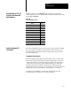
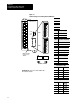
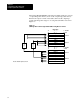
When using discrete transfer, each analog block I/O module uses 4 words
of output image table memory and 4 words of input image table memory.
Each block occupies 1/2 rack of data table, with 2 blocks comprising 1
logical rack. Image table usage for one assigned rack number is shown in
Figure 3.3.
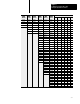
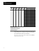
Figure 3.3
I/O
Image Table for One Assigned Rack Number using Discrete T
ransfer
Output Image
Input Image
0
1
2
3
4
5
6
7
017
0
1
2
3
4
5
6
7
710
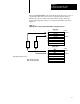
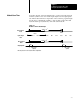
1791N4C2
PLC
SLC 50007815
SLC 50007815
017 710
PLC
Input 0
Input 1
Input 2
Input 3
1/2 Rack
1/2 Rack
Output 0
Output 1
1/2 Rack
Discrete transfer requires 1/2 rack.
Reserved
1/2 Rack
1791N4C2
Output 0
Output 1
Reserved
Input 0
Input 1
Input 2
Input 3
Configuration
Configuration