
Instruction Manual

Configuring Your Block I/O for PLC
Family Programmable Controllers
Chapter 3
3-4
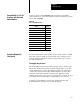
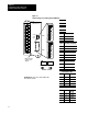
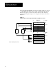
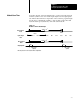
SW1 Switch Position
PLC3
Rack
Number
PLC5/250
Rack
Number
PLC5
Rack
Number
PLC2
Rack
Number
1771SN
Rack
Number
1747SN
Rack
Number
345678
PLC3
Rack
Number
PLC5/250
Rack
Number
PLC5
Rack
Number
PLC2
Rack
Number
1771SN
Rack
Number
1747SN
Rack
Number
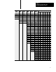
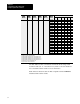
Rack
51
1 0 1 0 0 1
Rack 52
1 0 1 0 1 0
Rack 53
1 0 1 0 1 1
Rack 54
1 0 1 1 0 0
Rack 55
1 0 1 1 0 1
Rack 56
1 0 1 1 1 0
Rack 57
1 0 1 1 1 1
Rack 60
1 1 0 0 0 0
Rack 61
1 1 0 0 0 1
Rack 62
1 1 0 0 1 0
Rack 63
1 1 0 0 1 1
Rack 64
1 1 0 1 0 0
Rack 65
1 1 0 1 0 1
Rack 66
1 1 0 1 1 0
Rack 67
1 1 0 1 1 1
Rack 70
1 1 1 0 0 0
Rack 71
1 1 1 0 0 1
Rack 72
1 1 1 0 1 0
Rack 73
1 1 1 0 1 1
Rack 74
1 1 1 1 0 0
Rack 75
1 1 1 1 0 1
Rack 76
1 1 1 1 1 0
Not V
alid 1 1 1 1 1 1
Rack
address 77 is an illegal configuration.
PLC5/1
1 processors can scan rack 03.
PLC5/15 and PLC5/20 processors can scan racks 0103.
PLC5/25 and PLC5/30 processors can scan racks 0107.
PLC5/40 and PLC5/40L processors can scan racks 0117.
PLC5/60 and PLC5/60L processors can scan racks 0127.
PLC5/250 processors can scan racks 037.
PLC3 processors can scan racks 076.
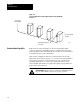
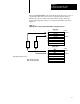
The SLC 500 controllers communicate with the block I/O using an I/O
Scanner module (cat. no. 1747-SN series A). Refer to the user manual for
the 1747-SN/A Scanner module for more information.
Note: These block I/O modules are not compatible with the 1747-DSN
Distributed I/O Scanner module.