
Instruction Manual

Installing Block I/O
Chapter 2
2-13
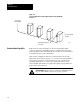
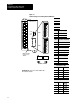
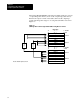
A termination resistor must be installed on the last block in a series.
Connect the resistor as shown in Figure 2.11.
Figure 2.11
Installing
the T
ermination Resistor
Termination
Resistor
Connect termination resistor across
terminals 6 (BLU) and 8 (CLR).
10835I
BLU
SHD
CLR
Refer to Table 2.A for proper
terminator for your application.
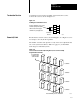
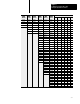
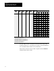
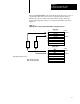
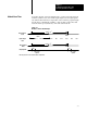
Blocks must be wired in series as shown in Figure 2.12 or Figure 2.13. Do
not attempt to wire any block in parallel.
The number of blocks used depends not only on the user requirements but
also on the system used. Refer to Table 2.A (page 2-1) for maximum
block usage for individual systems.
Figure 2.12
Series
Connection for Block I/O Using PLC2, PLC3 or PLC5 Family
Programmable Controllers
Install terminating resistor on last block.
To Programmable
Controller or I/O
Scanner Module
1 I/O Rack
1 I/O Rack
1 I/O Rack
1 I/O Rack
10833I
Termination Resistor
Remote I/O Link