
Instruction Manual
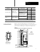
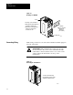

Installing Block I/O
Chapter 2
2-9
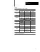
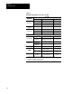
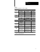
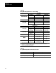
Table 2.B
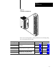
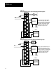
Wiring
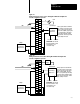
Block Designations for Cat. No. 1791N4V2
Connections
1791-N4V2
Connections
Designation Description Terminal No.
Power
L1 ac hot 1
Power
Connections
N
ac neutral 3
GND Chassis ground 2
1
Transducer
Power
2
+24V For current input only 25
Remote I/O
BLU Blue wire - RIO 6
Remote
I/O
Connections
CLR
Clear wire - RIO 8
SHD Shield - RIO 7
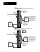
I/O Connections
inV0 thru inV3 Voltage Input 0 through 3 9, 13, 17, 21
Voltage Input
RET in0 thru
RET in3
Input Return 0 through 3 10, 14, 18, 22
inI0 thru inI3 Current Input 0 through 3 11, 15, 19, 23
Current Input
RET in0 thru
RET in3
Input Return 0 through 3 10, 14, 18, 22
Input Ground GNDin0GNDin3 Channels 03 ground 12, 16, 20, 24
3
Output
out 0 - RET out 0
Output 0 (+)
Return output 0 (-)
27
26
4
Output
out 1 - RET out 1
Output 1 (+)
Return output 1 (-)
29
28
4
Not used
For internal test only; not
for customer use.
4, 5, 30
1
Connect
chassis ground to equipment grounding stud. These are not internally connected.
2
2028V dc (nominal 24V, 100mA)) voltage source for accommodating looppowered current transducer inputs.
3
Terminals
12, 16, 20, and 24 are internally connected.
4
T
erminals 26 and 28 internally connected together
.