
Instruction Manual

Installing Block I/O
Chapter 2
2-5
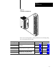
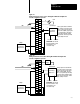
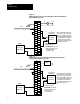
Figure 2.4
Terminal
Block Pin Numbering
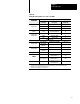
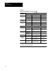
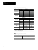
Refer to the following table for wiring schematics and connecting wiring
lists for the analog block modules.
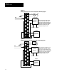
Power Supply Voltage Input For Schematic refer to: For wiring refer to:
120V ac
Wiring Connections for the Analog Block with
Figure 2.5, page 26 Table 2.B, page 29
24V dc
Wiring Connections for the Analog Block with
Voltage Inputs
Figure 2.6, page 26 Table 2.C, page 210
120V ac
Wiring Connections for the Analog Block with
Figure 2.7, page 27 Table 2.D, page 211
24V dc
Wiring Connections for the Analog Block with
Current Input and CustomerSupplied Loop Power
Figure 2.8, page 27 Table 2.E, page 212
120V ac
Wiring Connections for the Analog Block with
Figure 2.9, page 28 Table 2.D, page 211
24V dc
Wiring Connections for the Analog Block with
Current Input and BlockSupplied Loop Power
Figure 2.10, page 28 Table 2.E, page 212