
Instruction Manual

Chapter
2
2-1
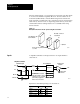
Installing Block I/O
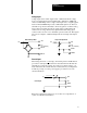
In this chapter, you will learn how to mount the block, connect the remote
I/O link, connect the input and output wiring to the block, and terminate
the remote I/O link.
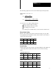
Before installation, you must determine the:
scanner/processor to use
number of blocks on your network
throughput requirements
total distance of the installation
transmission rate desired
external fuses required (if any)
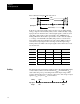
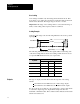
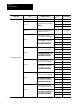
Acceptable combinations are shown in Table 2.A.
Table 2.A
Acceptable
Combinations of Processor and Block I/O
When using and Maximum Capacity
Baud Rate
Used
Maximum
Network Distance
1771
SN
14 blocks with 150 ohm terminator
57.6K 10,000 cablefeet
PLC
2 family
1
77
1
SN
14
blocks
with
150
ohm
terminator
and discrete transfer
115.2K 5,000 cablefeet
PLC
2
f
am
il
y
1772
SD 1772
SD2
16 blocks/channel, 28 blocks/scanner
57.6K 10,000 cablefeet
1
77
2
SD
,
1
77
2
SD2
16
blocks/channel
,
28
blocks/scanner
with 150 ohm terminator
115.2K 5,000 cablefeet
Any PLC
3 scanner module
16 blocks/channel, 64 blocks/scanner
with 150 ohm terminator. 128 blocks
57.6K 10,000 cablefeet
PLC 3 f il
A
ny
PLC
3
scanner mo
d
u
l
e
with
150
ohm
terminator
.
128
blocks
with 2 scanners and 150 ohm
terminator.
115.2K 5,000 cablefeet
PLC3 family
32 blocks/channel, 64 blocks/scanner
57.6K 10,000 cablefeet
1775S5, or SR5 module
32
blocks/channel
,
64
blocks/scanner
with 82 ohm terminator. 128 blocks
with 2 scanners, 82 ohm terminator
115.2K 5,000 cablefeet
with
2
scanners
,
82
ohm
terminator
and extended node addressing.
230.4K 2,000 cablefeet
PLC5VME (6008LTV)
4 blocks with 150 ohm terminator
57.6K 10,000 cablefeet
PLC
5 family
57.6K 10,000 cablefeet
PLC
5
f
am
il
y
PLC5/11
4 blocks with 150 ohm terminator
115.2K 5,000 cablefeet
230.4K 2,500 cablefeet
Chapter
Objectives
Preinstallation
Considerations