
Instruction Manual

Introducing Block I/O
Chapter 1
1-11
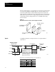
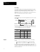
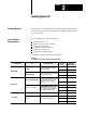
The output sacrifices a small amount of the resolution to provide a margin
of 2.5% to allow for system or calibration inaccuracies as shown below.
13 Bits
12.9 Bits
Nominal Range
20.5 20 10 0.0 –0.5
Resolution
Input Signal
Margin
Margin
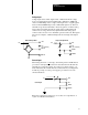
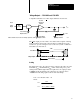
Scaling
The digital data sent to the output is always scaled by the values set in the
maximum (S
max
) and minimum (S
min
) scaler values using a two point
scaling method. When digital data sent equals S
max
, the output produces
20.000mA and the digital data sent equals S
min
, the output produces
0.000mA. The following equations shows this relationship:
Iout
= M x Module Data + B
where:
20mA
(Smax – Smin)
20mA x (Smax + Smin)
M =
B =
(Smax – Smin)
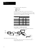
You can choose one of three scaling methods:
binary counts
default scaling
user scaling
User scaling is not available when you select discrete transfer mode.
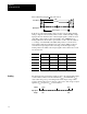
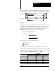
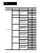
The following table shows the output signals produced by various module
data values entered in each of the three scaling methods. In the user scaling
column, S
max
was set to 5000 and S
min
was set to 0000.
Output Signal
Module Data
Output Signal
Binary Counts Scaling Default Scaling User Scaling
Nominally +20.5mA 8395 10250 5062
20.000mA 8191 10000 5000 (Smax)
0.000mA 0000 00000 2500 (Smin)
Nominally -0.5mA
1
-0396 -00050 -2437
1
The actual output can never go negative. However
, some of the output range is used to allow for zero of
fset
compensation.