
Instruction Manual

Introducing Block I/O
Chapter 1
1-7
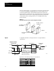
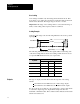
The following equation shows how the module interprets the input data:
Module
data = M x V
in
+ B
where:
(S
max
– S
min
)
(V
nfs
– V
nbs
)
M =
(S
min
x V
nfs
) – (S
max
x V
nbs
)
(V
nfs
– V
nbs
)
B =
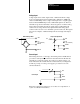
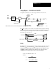
You can choose one of three scaling methods:
binary counts (module sets scalers)
default scaling (module sets scalers)
user scaling (you set scalers)
User scaling is not available when you select discrete transfer mode.
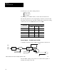
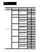
Binary Counts Scaling
Binary counts scaling mode activates when the module powers up. This
mode guarantees the maximum resolution. The module sets the scalers as
shown in the following table:
Scaler +/-10V 0-10V +/-5V 0-5V
S
max
8191 16383 8191 16383
S
min
-8192 0 -8192 0
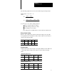
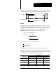
Default Scaling
Default scaling mode scales inputs to the input stimulus in either millivolts
or microamps. The module sets the scalers as shown in the following
tables:
With Voltage Input Selected
Scaler +/-10V 0-10V +/-5V 0-5V
S
max
10,000mV 10,000mV 5000mV 5000mV
S
min
-10,000mV 0mV -5000mV 0mV
With Current Input Selected
Scaler +/-10V 0-10V +/-5V 0-5V
S
max
N/A N/A 20000uA 20000uA
S
min
N/A N/A -20000uA 0uA