
Instruction Manual

Introducing Block I/O
Chapter 1
1-6
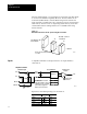
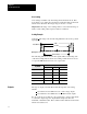
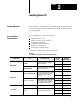
This is illustrated using the +10V scale below:
14 Bits
13.96 Bits
Nominal Range
I1 I2 I3 I4 I5
Resolution
Input Signal
Margin
Margin
In the above scale, input signals 1 thru 5 produce corresponding internal
analog to digital converter (ADC) binary counts. A full scale (FS) voltage
input produces an internal count of 16383 (input signal 1), while a bottom
scale (BS) voltage input produces an internal count of 0000 (input 5).
During calibration, the module’s representation of the counts are adjusted
so a voltage of nominal full scale (NFS) will produce a count shown as
input signal 2 while the nominal bottom scale voltage (NBS) produces a
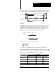
count shown as input signal 4. For each range scale, the input voltage
which produces the ADC count of input signals 1 thru 5 in the above scale
are shown below:
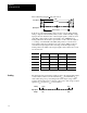
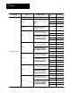
Input Signal +/-10V 0-10V +/-5V 0-5V
I1 10.25V (FS) 10.25V (FS) 5.125V (FS) 5.125V (FS)
I2 +10.000V (NFS) 10.00V (NFS) 5.000V (NFS) 5.000V (NFS)
I3 0.000V 5.00V 0.000V 2.500V
I4 -10.000V (NBS) 0.00V (NBS) -5.000V (NBS) 0.000V (NBS)
I5 -10.25V (BS) -0.25V (BS) -5.125V (BS) -0.125V (BS)
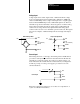
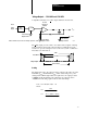
The input data represented at the module is always the internal ADC binary
counts scaled by values set in the maximum (S
max
) and minimum (S
min
)
scaler value using a two point scaling method. The input voltage which
produces input signal 2 (V
nfs
) is always equal to S
max
, and voltage of input
signal 4 (V
nbs
) is equal to S
min
as shown below:
Scaling
Voltage
Vnfs
Vnbs
Smax
Smin
I1 I2 I3 I4 I5
Input Signal
Scaling