791 Analog Block I/O Input/Output Modules User Manual
Important User Information Because of the variety of uses for the products described in this publication, those responsible for the application and use of this control equipment must satisfy themselves that all necessary steps have been taken to assure that each application and use meets all performance and safety requirements, including any applicable laws, regulations, codes and standards. The illustrations, charts, sample programs and layout examples shown in this guide are intended solely for example.
Summary of Changes Summary of Changes Summary of Changes This release of the publication contains new and updated information from the last release. New Information This release includes information on new block I/O modules now available. This information was not included in the previous release of this publication.
Table of Contents Summary of Changes . . . . . . . . . . . . . . . . . . . . . . . . . . . . S 1 Using This Manual . . . . . . . . . . . . . . . . . . . . . . . . . . . . . . . P 1 Purpose of Manual . . . . . . . . . . . . . . . . . . . . . . . . . . . . . . . . . . . Audience . . . . . . . . . . . . . . . . . . . . . . . . . . . . . . . . . . . . . . . . . . Vocabulary . . . . . . . . . . . . . . . . . . . . . . . . . . . . . . . . . . . . . . . . Manual Organization . . . . . . . . . . . . . . . . .
ii Table of Contents Analog Block Applications Using Discrete Transfers . . . . . 5 1 Chapter Objectives . . . . . . . . . . . . . . . . . . . . . . . . . . . . . . . . . . . Discrete Data Transfer . . . . . . . . . . . . . . . . . . . . . . . . . . . . . . . . Input Data Format . . . . . . . . . . . . . . . . . . . . . . . . . . . . . . . . . . . Output Data Format . . . . . . . . . . . . . . . . . . . . . . . . . . . . . . . . . . 5 1 5 1 5 1 5 2 Programming Your Analog Block I/O Module . . . . . .
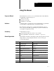
Preface Using This Manual Purpose of Manual This manual shows you how to use your block I/O with an Allen-Bradley programmable controller. It helps you: install your module program your module troubleshoot your module Audience You must be able to program and operate an Allen-Bradley programmable controller (PLC) to make efficient use of block I/O modules. We assume that you know how to do this in this manual.
Preface Using This Manual Block I/O Products Covered by this Publication Related Publications P-2 This publication covers the following analog block I/O products: Catalog Number Power Supply Voltage Inputs Outputs Description 1791 N4V2 120V ac 4 2 analog - 4 input, 2 voltage output 1791 N4C2 120V ac 4 2 analog - 4 input, 2 current output 1791 NDV 24V dc 4 2 analog - 4 input, 2 voltage output 1791 NDC 24V dc 4 2 analog - 4 input, 2 current output For a list of publications with
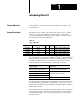
Chapter 1 Introducing Block I/O Chapter Objectives In this chapter, you will learn what analog block I/O is, its features, and how it functions. General Description Block I/O consists of small, self-contained remote I/O devices complete with power supply, programmable controller interface, input/output connections and signal conditioning circuitry. Table 1.A is a list of block I/O modules covered in this publication. Table 1.
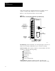
Chapter 1 Introducing Block I/O Analog block outputs are configured at the factory for either a current output or a voltage output. Outputs are not user-configurable. Figure 1.1 shows the physical features of the block I/O. Figure 1.
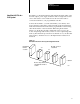
Chapter 1 Introducing Block I/O How Block I/O Fits in a PLC System Block I/O is a complete I/O interface that includes the functionality of the I/O rack, adapter, power supply, and I/O module in a single unit. Connect sensors and actuators to the module and use the remote I/O cable to connect the block I/O to your programmable controller. Connect the block I/O to your remote I/O link as you would any other device.
Chapter 1 Introducing Block I/O Discrete transfer (Figure 1.3) is intended to be used with controllers which do not have block transfer capability. However, discrete transfer can be used with any PLC family controller. When using discrete transfer, the block looks like a 1/2 I/O rack to the controller (four words of input image table memory and four words of output image table memory). Note that certain alarms and user scaling features are not available when using discrete transfer. Figure 1.
Chapter 1 Introducing Block I/O Voltage Input Voltage inputs can be either single-ended or differential. In the voltage mode, a signal applied between inV0 and the combination of RET in0 shorted to GND in0 provides a single-ended input mode. A signal applied between inV0 and RET in0 provides a differential input mode. The four terminals for ground are internally connected together to form the analog input common.
Chapter 1 Introducing Block I/O This is illustrated using the +10V scale below: Input Signal Margin I1 Margin 14 Bits Resolution 13.96 Bits I2 I3 I4 I5 Nominal Range In the above scale, input signals 1 thru 5 produce corresponding internal analog to digital converter (ADC) binary counts. A full scale (FS) voltage input produces an internal count of 16383 (input signal 1), while a bottom scale (BS) voltage input produces an internal count of 0000 (input 5).
Chapter 1 Introducing Block I/O The following equation shows how the module interprets the input data: Module data = M x Vin + B where: (Smax – Smin) M = B = (Vnfs – Vnbs) (Smin x Vnfs) – (Smax x Vnbs) (Vnfs – Vnbs) You can choose one of three scaling methods: binary counts (module sets scalers) default scaling (module sets scalers) user scaling (you set scalers) User scaling is not available when you select discrete transfer mode.
Chapter 1 Introducing Block I/O User Scaling User scaling is available only when using the block transfer mode. This mode allows you to define Smax and Smin in engineering units in the block transfer write data table. The integer range is 32,767 to –32,768. Important: If the range of user scaling values is set less than the range of binary counts scaling values, input resolution is sacrificed. Scaling Example Using the +10V range scale, the following illustration shows five possible input signals.
Chapter 1 Introducing Block I/O Voltage Outputs - 1791 N4V2 and 1791 NDV A simplified schematic of a +10V output channel is shown below. Precision Operational Amplifier VOUTS Digital Output Opto Isolation DAC + VOUT 2 VRET Note: Schematic does not show overvoltage protection circuits. Isolated Analog Output Common 2 2 Isolated Analog Output Common 12501-I The +10V output provides 14 bits of resolution and is capable of driving loads as small as 1k ohm.
Chapter 1 Introducing Block I/O You can choose one of three scaling methods: binary counts default scaling user scaling User scaling is not available when you select discrete transfer mode. The following table shows the output signals produced by various module data values entered in each of the three scaling methods. In the user scaling column, Smax was set to 5000 and Smin was set to 0000. Module Data Output Signal Binary Counts Scaling Default Scaling User Scaling Approx. +10.
Chapter 1 Introducing Block I/O The output sacrifices a small amount of the resolution to provide a margin of 2.5% to allow for system or calibration inaccuracies as shown below. Input Signal 20.5 Margin 13 Bits Margin Resolution 12.9 Bits 20 10 0.0 –0.5 Nominal Range Scaling The digital data sent to the output is always scaled by the values set in the maximum (Smax) and minimum (Smin) scaler values using a two point scaling method. When digital data sent equals Smax, the output produces 20.
Chapter 2 Installing Block I/O Chapter Objectives In this chapter, you will learn how to mount the block, connect the remote I/O link, connect the input and output wiring to the block, and terminate the remote I/O link.
Chapter 2 Installing Block I/O When using and PLC 5/151 PLC 5/20 PLC 5/252 Maximum Capacity 12 blocks with 150 ohm terminator 12 blocks with 82 ohm or 150 ohm terminator PLC 5 family (continued) 2-2 10,000 cable feet 115.2K 5,000 cable feet 230.4K 2,500 cable feet 115.2K 5,000 cable feet 57.6K 10,000 cable feet 115.2K 5,000 cable feet 230.4K 2,500 cable feet 57.6K 10,000 cable feet 115.2K 5,000 cable feet 57.6K 10,000 cable feet 115.2K 5,000 cable feet 230.
Chapter 2 Installing Block I/O When using and Baud Rate Used Maximum Capacity 16 blocks/channel, 32 blocks/scanner (128 blocks with 4 blocks/scanner, scanners) with 150 ohm terminator PLC 5 family (continued) S C / (and greater) SLC 5/02 Controller PLC 5/250 requires i PLC 5/250 5 50 S remote e o e scanner sca e a 5150 RS 32 blocks/channel, 32 blocks/scanner, (128 blocks with 4 scanners) with 82 ohm terminator and extended node addressing S Remote I/O /O Scanner S 1747 SN Module (discrete mode on
Chapter 2 Installing Block I/O Figure 2.2 Mounting on a DIN Rail Block 1. Hook top of slot over DIN rail. 2. While pressing block against rail, pull down on locking lever. 3. When block is flush against rail, push up on locking lever to secure block to rail. DIN Rail A B pt. no. 199 DR1 DIN 46277 3 EN 50022 (3.4 x 7.5mm) Locking Lever 12382 I Connecting Wiring Make wiring connections to the removable terminal block which plugs into the front of the block.
Chapter 2 Installing Block I/O Figure 2.4 Terminal Block Pin Numbering Refer to the following table for wiring schematics and connecting wiring lists for the analog block modules.
Chapter 2 Installing Block I/O Figure 2.5 Wiring Connections for the 120V ac Analog Block with Voltage Inputs 1 GND RIO NOT USED BLU CLR RET in0 GND in0 RET in1 N NOT USED SHD in V1 in I1 GND in2 RET in3 in V3 NOT USED Analog signals must be within the 10V common mode voltage range which is referenced to the analog input common (GND). Typically, this is accomplished by connecting to user ground. If an input channel floats outside of this range, invalid input readings will result.
Chapter 2 Installing Block I/O Figure 2.7 Wiring Connections for the 120V ac Analog Block with Current Input and Customer Supplied Loop Power 1 GND NOT USED RIO BLU CLR RET in0 Output User Analog Output Device - in V0 in V2 GND in2 RET in3 in V3 Analog signals must be within the 10V common mode voltage range which is referenced to the analog input common (GND). Typically, this is accomplished by connecting to user ground.
Chapter 2 Installing Block I/O Figure 2.
Chapter 2 Installing Block I/O Table 2.B Wiring Block Designations for Cat. No. 1791 N4V2 Connections Power Connections 1791-N4V2 Designation Description Terminal No.
Chapter 2 Installing Block I/O Table 2.C Wiring Block Designations for Cat. No. 1791 NDV Connections Power Connections 1791-NDV Designation Description Terminal No.
Chapter 2 Installing Block I/O Table 2.D Wiring Block Designations for Cat. No. 1791 N4C2 Connections Power Connections Transducer Power2 Remote I/O Connections 1791-N4C2 Designation Description Terminal No.
Chapter 2 Installing Block I/O Table 2.E Wiring Block Designationsfor Cat. No. 1791 NDC Connections Power Connections 1791-NDC Designation Description Terminal No.
Chapter 2 Installing Block I/O Termination Resistor A termination resistor must be installed on the last block in a series. Connect the resistor as shown in Figure 2.11. Figure 2.11 Installing the Termination Resistor Connect termination resistor across terminals 6 (BLU) and 8 (CLR). BLU Refer to Table 2.A for proper terminator for your application. CLR Termination Resistor Remote I/O Link SHD 10835 I Blocks must be wired in series as shown in Figure 2.12 or Figure 2.13.
Chapter 2 Installing Block I/O Figure 2.13 Series Configurations for Block I/O Using the SLC Programmable Controller To 1747 SN Scanner Module 1 2 7 8 Up to 8 blocks with SLC 5/02 Install terminating resistor on last block. Extended Node Capability 10834 I If this is the last remote I/O adapter on the remote I/O link in a PLC system, you must use a terminating resistor to terminate both ends of the remote I/O link (scanner end and last block end).
Chapter 2 Installing Block I/O Compatibility of 1771 I/O Products with Extended Node Numbers Certain products are not compatible with extended node capabilities obtained with the use of 82 ohm terminators. Table 2.G lists those products that are not compatible. Table 2.
Chapter 3 Configuring Your Block I/O for PLC Family Programmable Controllers Chapter Objectives In this chapter, you will learn how to configure your block I/O when used with PLC family programmable controllers.
Chapter 3 Configuring Your Block I/O for PLC Family Programmable Controllers Figure 3.
Chapter 3 Configuring Your Block I/O for PLC Family Programmable Controllers 1747 SN Rack Number 1771 SN Rack Number PLC 2 Rack Number PLC 5 Rack Number PLC 5/250 Rack Number PLC 3 Rack Number 8 7 6 5 4 3 Rack 0 Rack 1 Rack 1 Not Valid Rack 0 Rack 0 0 0 0 0 0 0 Rack 1 Rack 2 Rack 2 Rack 1 Rack 1 Rack 1 0 0 0 0 0 1 Rack 2 Rack 3 Rack 3 Rack 2 Rack 2 Rack 2 0 0 0 0 1 0 Rack 3 Rack 4 Rack 4 Rack 3 Rack 3 Rack 3 0 0 0 0 1 1 Rack 5 Rack 5 Rack 4 Rac
Chapter 3 Configuring Your Block I/O for PLC Family Programmable Controllers 1747 SN Rack Number 1771 SN Rack Number PLC 2 Rack Number PLC 5 Rack Number PLC 5/250 Rack Number PLC 3 Rack Number 8 7 6 5 4 3 Rack 51 Rack 52 Rack 53 Rack 54 Rack 55 Rack 56 Rack 57 Rack 60 Rack 61 Rack 62 Rack 63 Rack 64 Rack 65 Rack 66 Rack 67 Rack 70 Rack 71 Rack 72 Rack 73 Rack 74 Rack 75 Rack 76 Not Valid 1 1 1 1 1 1 1 1 1 1 1 1 1 1 1 1 1 1 1 1 1 1 1 0 0 0 0 0 0 0 1 1 1 1 1 1 1 1 1 1 1 1 1 1 1 1 1 1 1 1 1 1 1
Chapter 3 Configuring Your Block I/O for PLC Family Programmable Controllers When using block transfer, each analog block I/O module uses 2 words of output image table memory and 2 words of input image table memory. Each block occupies 1/4 rack of data table, with 4 blocks comprising 1 logical rack. Image table usage for one assigned rack number is shown in Figure 3.3. Figure 3.
Chapter 3 Configuring Your Block I/O for PLC Family Programmable Controllers When using discrete transfer, each analog block I/O module uses 4 words of output image table memory and 4 words of input image table memory. Each block occupies 1/2 rack of data table, with 2 blocks comprising 1 logical rack. Image table usage for one assigned rack number is shown in Figure 3.3. Figure 3.3 I/O Image Table for One Assigned Rack Number using Discrete Transfer Discrete transfer requires 1/2 rack.
Chapter 3 Configuring Your Block I/O for PLC Family Programmable Controllers Module Scan Time Scan time depends on the block transfer rate over the remote I/O network, which is asynchronous to the module input sample rate and output update rate. The block transfer rate is dependent on the controller, program length, the amount of communication traffic to other modules on the remote I/O network and the speed (baud rate) of the remote I/O network. Figure 3.
Chapter 4 Analog Block Applications Using Block Transfers Chapter Objectives In this chapter, you will read about: reading data and status from the module block transfer read data format configuring the module and setting outputs with block transfer write instructions Reading Data and Status from the Module Block transfer instructions are used when the analog block is used with PLC programmable controllers with block transfer capability.
Chapter 4 Analog Block Applications Using Block Transfers Table 4.A Bit/Word Descriptions for Block Transfer Read Instruction Word Decimal Bit (Octal Bit) Description Bits 15 (17) Power up (PU) status bit. This bit is set (1) if the module has not been configured since the last power up. It is reset (0) when at least one valid BTW has occurred since power up. Outputs are not enabled until the PU bit is reset. Bit 14 (16) Bad configuration (BC) bit.
Chapter 4 Analog Block Applications Using Block Transfers Configuring the Module and Setting Outputs with Block Transfer Write Instructions You must configure your block module by performing a block transfer write (BTW) instruction from the programmable controller to the module. Each input can be independently configured in one BTW. Maximum length of the BTW is 27 words (0 thru 26). When configuring the module, first send the complete BTW.
Chapter 4 Analog Block Applications Using Block Transfers The bit/word descriptions are shown in Table 4.B. Table 4.B Bit/Word Descriptions for the Block Transfer Write Instruction Word Decimal Bit (Octal Bit) Description Module Mode. Bits 12 15 (14 17) determine the operation of the block module.
Chapter 4 Analog Block Applications Using Block Transfers Word Decimal Bit (Octal Bit) Word 1 Bits 00 15 (00 17) Output data for channel 0. Word 2 Bits 00 15 (00 17) Output data for channel 1. Word 3 Bits 00 15 (00 17) Minimum engineering scale factors for output channel 0 data. Word 4 Bits 00 15 (00 17) Maximum engineering scale factors for output channel 0 data. Word 5 Bits 00 15 (00 17) Minimum engineering scale factors for output channel 1 data.
Chapter 4 Analog Block Applications Using Block Transfers Word Decimal Bit (Octal Bit) Word 25 Bits 00 15 (00 17) High alarm level for input channel 3. When the input value for this channel is greater than the high value, the corresponding high alarm bit is set in the BTR. Bits 00 15 (00 17) Alarm deadband for input channel 3. This field creates a hysteresis effect on the low and high alarms.
Chapter 5 Analog Block Applications Using Discrete Transfers Chapter Objectives In this chapter you will read about: discrete data transfer input data format output data format Discrete Data Transfer When used with SLC controllers, analog block data is transferred as discrete data using the 1747-SN remote I/O scanner module. The analog block uses 1/2 rack of memory in the I/O data table. The transferred words in the input image data table contain only input data from the module.
Chapter 5 Analog Block Applications Using Discrete Transfers Table 5.A Input Image Table Output Data Format Word Bit - Decimal (Bit - Octal) Word 0 Bits 00-15 (00-17) Input data for channel 0. Word 1 Bits 00-15 (00-17) Input data for channel 1. Word 2 Bits 00-15 (00-17) Input data for channel 2. Word 3 Bits 00-15 (00-17) Input data for channel 3. Description The output image table data format consists of four words.
Chapter 5 Analog Block Applications Using Discrete Transfers Table 5.B Bit/Word Descriptions for Discrete Data Transfer - Output Table 1/2 Rack Word Decimal Bit (Octal Bit) Bit 15 (17) Bits 12-14 12 14 (14-16) Word 0 Bit 11 ((13) 3) Description Output Enable Bit OE Bit 15 (17) 0 Outputs are held at 0. Note: To calibrate, you must set the Output Enable Bit to 1 (refer to Chapter 7). 1 Both outputs are enabled. Module Mode. Bits 12 thru 14 determine the operation of the block module.
Chapter 5 Analog Block Applications Using Discrete Transfers Table 5.C Filter Time Selection Filter Time 5-4 Bit Settings Bit 03 Bit 02 Bit 01 Bit 00 Default - no filter 0 0 0 0 Do not use.
Chapter 6 Programming Your Analog Block I/O Module Chapter Objectives In this chapter, we describe block transfer programming sample programs in the PLC-3 and PLC-5 processors module scan time issues Block Transfer Programming Your module communicates with the processor through bidirectional block transfers. This is the sequential operation of both read and write block transfer instructions. For the analog block I/O modules, block transfer writes (BTWs) can perform two different functions.
Chapter 6 Programming Your Analog Module PLC 3 Program Example Block transfer instructions with the PLC-3 processor use one binary file in a data table section for module location and other related data. This is the block transfer control file. The block transfer data file stores data that you want transferred to the module (when programming a block transfer write) or from the module (when programming a block transfer read).
Chapter 6 Programming Your Analog Module PLC 5 and PLC-5/250 Program Example This program is very similar to the PLC-3 program with the following exceptions: Use enable bits instead of done bits as the conditions on each rung. Use separate control files for each block transfer instruction. Refer to Appendix B. Figure 6.
Chapter 6 Programming Your Analog Module Sample Programs for Analog Block The following are sample programs for using your modules more efficiently when operating with the PLC-3 or PLC-5 family processors. These programs show you how to: configure the module read data from the module update the output channels Refer to the proper PLC-3 or PLC-5 documentation for additional information on processor programming and data entry.
Chapter 6 Programming Your Analog Module PLC 5 Family Processors The following PLC-5 program is very similar to the PLC-3 program with the following exceptions: You must use enable bits instead of done bits as the conditions on each rung. Rungs 2 and 3 have been replaced with 1 rung. A separate control file must be selected for each of the block transfer instructions. Figure 6.
7 Chapter Module Calibration Chapter Objective In this chapter we tell you how to calibrate your module.
Chapter 7 Module Calibration Table 7.B Calibration Block Transfer Write or Discrete Output Bit/Word Descriptions Decimal Bit (Octal Bit) Word Word 0 Description Bit 00 Input select bit. Indicates input channel 0 being calibrated. Bit 01 Input select bit. Indicates input channel 1 being calibrated. Bit 02 Input select bit. Indicates input channel 2 being calibrated. Bit 03 Input select bit. Indicates input channel 3 being calibrated. Bit 04 Output select bit.
Chapter 7 Module Calibration Table 7.D Calibration Block Transfer Read or Discrete Input Bit/Word Descriptions Word Decimal Bit (Octal Bit) Description Bit 00 Input calibration error bit. When set, indicates input channel 0 calibration error. Bit 01 Input calibration error bit. When set, indicates input channel 1 calibration error. Bit 02 Input calibration error bit. When set, indicates input channel 2 calibration error. Bit 03 Input calibration error bit.
Chapter 7 Module Calibration Table 7.E Discrete Transfer Input Data File Word/Bit Description 0 Corrected Input Channel 0 Data 1 Corrected Input Channel 1 Data 2 Corrected Input Channel 2 Data 3 Corrected Input Channel 3 Data Table 7.F Discrete Transfer Input Bit/Word Descriptions Word/Bit Description 0 Corrected Input Data for Channel 0 using most recent calibration data. 1 Corrected Input Data for Channel 1 using most recent calibration data.
Chapter 7 Module Calibration Important: You can calibrate all four inputs simultaneously by wiring them in parallel. 2. Verify normal operation. 3. Select calibration mode, voltage input mode and the input channels you want to calibrate. For example, to calibrate input channel 0, set bits 15 (17), 14 (16) and 01 of BTW word 0 (C001h). 4. Apply 0.000V to inputs. 5. Set the EX bit (bit 07 of BTW word 0). For PLC systems: Monitor the DN bit (BTR word 0, bit 07) until it is set (1).
Chapter 7 Module Calibration 10. Set (1) the WR bit 11 (13) in BTW word 0. For PLC systems: Monitor the OK bit 11 (13) in BTR word 0 until it is set (1). For SLC systems: Allow at least 5 seconds before continuing. 11. Exit the calibration mode. Calibrating Current Inputs Use the procedure below to calibrate the current inputs on your analog block I/O module. The procedure can be used for either PLC or SLC systems.
Chapter 7 Module Calibration 5. Set the EX bit (bit 07 of BTW word 0). For PLC systems: Monitor the DN bit (BTR word 0, bit 07) until it is set (1). For SLC systems: Allow at least 5 seconds before continuing. 6. Reset (0) the EX bit (BTW word 0, bit 07) and set (1) the HL bit (BTW word 0, bit 06). 7. Apply full scale current (+20.000 milliamps) to the inputs you are calibrating. 8. Set (1) the EX bit. For PLC systems: Monitor the DN bit (BTR word 0, bit 07) until it is set (1).
Chapter 7 Module Calibration Calibrating Voltage Outputs (1791 N4V2 and 1791 NDV) Use the procedure below to calibrate voltage outputs of the analog block I/O module. The procedure can be used for either PLC or SLC systems. The most accurate results are obtained by installing an optional load resistor which approximates the output load for the intended application. Important: To allow the module to stabilize, energize the module for at least 30 minutes before calibrating. To calibrate your module: 1.
Chapter 7 Module Calibration 6. Reset (0) the EX bit (BTW word 0, bit 07) and set (1) the HL bit (BTW word 0, bit 06). 7. Measure the full scale point with a precision meter. Enter the measured voltage in millivolts into the BTW word (word 1 for channel 0, word 2 for channel 1). 8. Set (1) the EX bit. For PLC systems: Monitor the DN bit (BTR word 0, bit 07) until it is set (1). For SLC systems: Allow at least 5 seconds before continuing. 9.
Chapter 7 Module Calibration Calibrating Current Outputs (1791 N4C2 and 1791 NDC) Use the procedure below to calibrate current outputs of the analog block I/O module. The procedure can be used for either PLC or SLC systems. You can calibrate any single input or output individually or, you can calibrate them simultaneously. Important: To allow the module to stabilize, energize the module for at least 30 minutes before calibrating. To calibrate your module: 1.
Chapter 7 Module Calibration 6. Reset (0) the EX bit (BTW word 0, bit 07) and set (1) the HL bit (BTW word 0, bit 06). 7. Measure the full scale point with a precision meter. Enter the measured current in milliamps into the BTW word (word 1 for channel 0, word 2 for channel 1). 8. Set (1) the EX bit. For PLC systems: Monitor the DN bit (BTR word 0, bit 07) until it is set (1). For SLC systems: Allow at least 5 seconds before continuing. 9.
Chapter 7 Module Calibration Calibration Example for the 1791 N4V2 Block I/O Module The following example shows you how to calibrate the inputs and outputs for the 1791-N4V2 block I/O module. 1. For inputs – short all RET and GND together and short Vin0 thru Vin3 together. Connect voltage sources and meter between Vin and GND. For outputs – connect meter and load to each output. 2. Verify normal operation. 3. Set the terminal radix to hexidecimal and set BTW word 0 to C03Fh. 4.
8 Chapter Troubleshooting Chapter Objectives In this chapter you will learn about the indicators on the block I/O module, and how to use them to troubleshoot the unit. Module Indicators Each block I/O module has indicators (Figure 8.1) which provide indication of module status.
Chapter 8 Troubleshooting Table 8.A Troubleshooting Chart Indication Description Power OFF ON No power Power okay COMM OFF Communications not established ON Communication established Flashing Reset commands being received in Program mode FAULT OFF Normal ON Error (hardware or software), block power low Flashing COMM FAIL - communication cable disconnected, 100ms between valid frames, no more than 255 valid frames between valid frames addressed to block, 20ms idle time exceeded.
Index B block compatibility, 1 1 block I/O, 1 3 installing, 2 3 pre-installation, 2 1 block transfer, 1 1 E extended node capability, 2 14 F features, 1 2 block transfer instructions, 4 1 block transfer programming, 6 1 block transfer read, 4 1 bit/word descriptions, 4 2 block transfer write, 4 3, 6 1 bit/word descriptions, 4 4 filter time selections, 4 6 C calibration block transfer write, 7 1, 7 2, 7 3 current inputs, 7 6 current outputs (1791-N4C2 and -NDC), 7 10 tools, 7 1 voltage inputs, 7 4 volta
I–2 Index remote I/O link wiring, 2 13 S 1791-N4V2, A 3 1791-NDC, A 5 1791-NDV, A 7 status indicators, 1 2, 8 1 sample programs analog block, 6 4 PLC-3, 6 4 PLC-5, 6 5 switch assembly, 1 2 scaling, 1 6 terminal strip, 1 2 scaling methods, 1 7 binary counts, 1 7 default scaling, 1 7 user scaling, 1 8 scan time, 3 7 T termination resistor, 2 13 throughput requirements, 2 15 troubleshooting chart, 8 2 types of block I/O, 1 1 selectable input ranges, 1 4 series connections PLC, 2 13 SLC, 2 14 single-
Allen Bradley has been helping its customers improve productivity and quality for 90 years. A B designs, manufactures and supports a broad range of control and automation products worldwide. They include logic processors, power and motion control devices, man machine interfaces and sensors. Allen Bradley is a subsidiary of Rockwell International, one of the world's leading technology companies. With major offices worldwide.