
USER MANUAL Instruction Manual

Installing Block I/O
Chapter 2
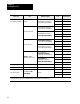
24
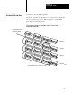
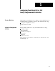
Figure 2.3
Input
and Output Connections for the 1791-IOBA/B
+24DCNCG VDCO0O1O2O3O4O5 I0 I1 I2 I3 I4 I5 I6 I7COM
8 OUTPUTS
8 INPUTS
INPUT 7
INPUT 6
INPUT 5
INPUT 4
INPUT 3
INPUT 2
OUTPUT 0
OUTPUT 1
OUTPUT 2
OUTPUT 3
OUTPUT 4
OUTPUT 5
INPUT 1
INPUT 0
+24V dc
dc Neutral
Output +Vdc
Chassis Ground
Input Common
O6O7
OUTPUT 6
OUTPUT 7
2SHD BACOM1
Remote
I/O Link
(see Figure 2.5)
DH-485
(for SLC
only)
10831-I
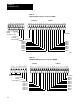
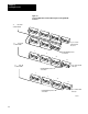
Figure 2.4
Input/Output
W
iring Connections for the 1791-IOBB/B
+24DCNCG VDCO0 O1 O2O3O4O5 I0 I1 I2 I3 I4 I5 I6 I7 I8 I9 COM
6 OUTPUTS
10 INPUTS
INPUT 9
INPUT 8
INPUT 7
INPUT 6
INPUT 5
INPUT 4
OUTPUT 0
OUTPUT 1
OUTPUT 2
OUTPUT 3
OUTPUT 4
OUTPUT 5
INPUT 3
INPUT 2
INPUT 1
INPUT 0
+24V dc
dc Neutral
Output +Vdc
Chassis Ground
Input Common
2SHD B ACOM1
Remote
I/O Link
DH-485
(for SLC only)