
USER MANUAL Instruction Manual


Chapter
2
21
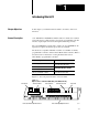
Installing Block I/O
In this chapter you will learn how to mount the block, connect the remote
I/O link, connect the input and output wiring to the block, and terminate
the remote I/O link.
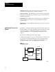
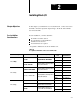
Before installation, you must determine:
the number of blocks desired
the total distance of the installation
transmission rate desired
if external fuses are required
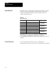
Acceptable combinations are shown in Table 2.A.
Table 2.A
Acceptable
Combinations of Processor and Block I/O
When using and Maximum Capacity
Baud Rate
Used
Maximum
Network Distance
1771
-
SN
16 blocks with 150 ohm terminator
57.6K 10,000 cable-feet
PLC
-
2 family
1
77
1
-
SN
16
bl
oc
k
s w
i
t
h
1
5
0
o
h
m term
i
nator
115.2K 5,000 cable-feet
PLC
-
2
f
am
il
y
1772
-
SD 1772
-
SD2
16 blocks/channel, 28 blocks/scanner
57.6K 10,000 cable-feet
1
77
2
-
SD
,
1
77
2
-
SD2
16
blocks/channel
,
28
blocks/scanner
with 150 ohm terminator
115.2K 5,000 cable-feet
Any PLC
-
3 scanner module
16 blocks/channel, 64 blocks/scanner
57.6K 10,000 cable-feet
A
ny
PLC
-
3
scanner mo
d
u
l
e
16
blocks/channel
,
64
blocks/scanner
with 150 ohm terminator
115.2K 5,000 cable-feet
PLC-3 family
//
57.6K 10,000 cable-feet
1775-S5, or -SR5 module
32 blocks/channel, 64 blocks/scanner
with 82 ohm terminator
115.2K 5,000 cable-feet
with
82
ohm
terminator
230.4K 2,000 cable-feet
PLC-5/15
12 blocks with 150 ohm terminator 57.6K 10,000 cable-feet
PLC-5 family
PLC-5/25
16 blocks with 150 ohm terminator,
28 blocks with 82 ohm terminator
57.6K 10,000 cable-feet
PLC 5
family
PLC
-
5/30
16 blocks/channel, 28 blocks per
57.6K 10,000 cable-feet
PLC
-5
/30
16
blocks/channel
,
28
blocks
per
processor with 150 ohm terminator
115.2K 5,000 cable-feet
Chapter
Objectives
Pre-installation
Considerations