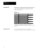
Block I/O Cat. No.
Important User Information Because of the variety of uses for the products described in this publication, those responsible for the application and use of this control equipment must satisfy themselves that all necessary steps have been taken to assure that each application and use meets all performance and safety requirements, including any applicable laws, regulations, codes and standards. The illustrations, charts, sample programs and layout examples shown in this guide are intended solely for example.
Important: We recommend you frequently backup your application programs on appropriate storage medium to avoid possible data loss.
Table of Contents Important User Information . . . . . . . . . . . . . . . . . . . . . . . . I Using This Manual . . . . . . . . . . . . . . . . . . . . . . . . . . . . . . . P 1 Purpose of Manual . . . . . . . . . . . . . . . . . . . . . . . . . . . . . . . . . . . Audience . . . . . . . . . . . . . . . . . . . . . . . . . . . . . . . . . . . . . . . . . . Vocabulary . . . . . . . . . . . . . . . . . . . . . . . . . . . . . . . . . . . . . . . . Manual Organization . . . . . . . . . . . . . . . . . .
Preface Using This Manual Purpose of Manual This manual shows you how to use your block I/O with an Allen–Bradley programmable controller. It helps you install, program and troubleshoot your module. Audience You must be able to program and operate an Allen–Bradley programmable controller (PLC) to make efficient use of block I/O modules. We assume that you know how to do this in this manual.
Preface Using This Manual About Block I/O Block I/O consists of small, self–contained remote I/O devices complete with power supply, programmable controller interface, input/output connections and signal conditioning circuitry. Table P.A is a list of available block I/O modules. Table P.
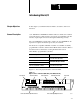
Chapter 1 Introducing Block I/O Chapter Objectives In this chapter you will learn what block I/O is, its features, and how it functions. General Description 1791–IOBA/B and –IOBB/B block I/O modules are small, self–contained remote I/O devices complete with power supply, programmable controller interface, input/output connections and signal conditioning circuitry. The 1791–IOBA/B has 8 inputs and 8 outputs; the 1791–IOBB/B has 10 inputs and 6 outputs. In all other aspects, they are identical.
Chapter 1 Introducing Block I/O Wiring Connectors – Remote I/O link connector and input/output connector are removable for easy connection of wiring. Switch Assemblies – Two DIP switches are provided for setting the I/O rack number, starting I/O group, transmission rate, last chassis, last state and DH–485 terminator. Status Indicators – LED indicators display the status of communication, power and input/output. These provide a visual indication for aid in troubleshooting.
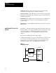
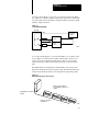
Chapter 1 Introducing Block I/O Sourcing outputs (Figure 1.3) have the power bussed in the block. When the output is on, current is supplied to the field control device, which sinks the current. The field circuit and the equipment remain at ground potential until the output is turned on. Figure 1.3 Sourcing Output Example Block I/O +VDC DC Power Supply Fuse Field Device Fuse Field Device -V 10827-I You connect the block I/O to your remote I/O link as you would any other device (Figure 1.4).
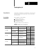
Chapter 2 Installing Block I/O Chapter Objectives In this chapter you will learn how to mount the block, connect the remote I/O link, connect the input and output wiring to the block, and terminate the remote I/O link. Pre-installation Considerations Before installation, you must determine: the number of blocks desired the total distance of the installation transmission rate desired if external fuses are required Acceptable combinations are shown in Table 2.A. Table 2.
Chapter 2 Installing Block I/O When using PLC-5 family (continued) and PLC-5/30 Maximum Capacity / 28 blocks/channel, 28 blocks per processor with 82 ohm terminator 16 blocks/channel, 32 blocks per processor with 150 ohm terminator PLC-5/40L, PLC-5/60L / 32 blocks/channel, 60 blocks per processor with 82 ohm terminator 16 blocks/channel, 60 blocks per processor with 150 ohm terminator PLC-5/40, PLC-5/60 / 32 blocks/channel, 60 blocks per processor with 82 ohm terminator 16 blocks/channel, 32 blocks/
Chapter 2 Installing Block I/O Installing the Block I/O Figure 2.1 shows the mounting dimensions for the block I/O module. Mount the blocks horizontally with a minimum of 2” between blocks. This air gap is necessary to maintain proper cooling air flow through the block. Figure 2.1 Mounting Dimensions for the Block I/O Module (Cat. No. 1791-IOBA/B and -IOBB/B) 10mm 0.39" Depth = 96.0mm (3.78") 8mm 0.31" 198mm 7.8" OUTPUT COMM POWER INPUT 35mm 1.37" 10mm 0.39" 180mm 7.1" 16mm 0.63" 16mm 0.
Chapter 2 Installing Block I/O Figure 2.3 Input and Output Connections for the 1791-IOBA/B 8 OUTPUTS 2 SHD 1 B A COM +24 DCN CG 8 INPUTS VDC O0 O1 O2 O3 O4 O5 O6 O7 I0 I1 I2 I3 I4 I5 I6 I7 COM Remote DH-485 I/O Link (for SLC (see Figure 2.5) only) +24V dc dc Neutral Chassis Ground Input Common Output +Vdc INPUT 7 INPUT 6 INPUT 5 INPUT 4 INPUT 3 INPUT 2 INPUT 1 INPUT 0 OUTPUT 0 OUTPUT 1 OUTPUT 2 OUTPUT 3 OUTPUT 4 OUTPUT 5 OUTPUT 6 OUTPUT 7 10831-I Figure 2.
Chapter 2 Installing Block I/O Table 2.
Chapter 2 Installing Block I/O Wiring Requirements Table 2.C shows the wiring cable requirements for the 1791–IOBA/B and 1791–IOBB/B modules. Table 2.C Acceptable Wiring Cables for Block I/O Connection Use Cable Type With Remote I/O Link or DIO Link Belden 9463 PLC-2, PLC-3, PLC-5 family programmable controllers and SLC controllers DH-485 Data Link Belden 9842 SLC controllers only Input and Output wiring Up to 14AWG Stranded with 3/64 inch insulation All Figure 2.
Chapter 2 Installing Block I/O Remote I/O Link or Distributed I/O Link Wiring Blocks must be wired in series as shown in Figure 2.6 or Figure 2.7. Do not attempt to wire any block in parallel. The number of blocks used depends not only on the user requirements but also on the system used. Refer to Table 2.A (page 2-1) for maximum block usage for individual systems. Figure 2.
Chapter 2 Installing Block I/O Figure 2.7 Series Configurations for Block I/O Using the SLC Programmable Controller To 1747-DSN Scanner Module Up to 7 blocks using SLC-5/01 Processor To 1747-DSN Scanner Module 1 Install terminating resistor on last block. 2 29 30 To 1747-SN Scanner Module Up to 30 blocks with SLC-5/02 Install terminating resistor on last block. 1 2 15 16 Install terminating resistor on last block.
Chapter 2 Installing Block I/O Termination Resistor A termination resistor must be installed on the last block in a series. Connect the resistor as shown in Figure 2.8. Use the resistor as identified in Table 2.D. Figure 2.8 Installing the Termination Resistor Tighten screw to clamp wires and termination resistor. Connect termination resistor across terminals 1 and 2 Termination Resistor 10835-I Table 2.
Chapter 2 Installing Block I/O Compatibility of 1771 I/O Products with Extended Node Numbers Certain products are not compatible with extended node capabilities obtained with the use of 82 ohm terminators. Table 2.E lists those products that are not compatible. Table 2.
Chapter 3 Configuring Your Block I/O for PLC Family Programmable Controllers Chapter Objectives In this chapter you will learn how to configure your block I/O when used with PLC family programmable controllers.
Chapter 3 Configuring Your Block I/O for PLC Family Programmable Controllers Figure 3.1 Switch Settings for 1791-IOBA/B and -IOBB/B S1 S2 OUTPUT COMM POWER INPUT Baud Rate 0 2 4 6 Switch 1 2 On (Closed) On (Closed) Off (Open) On (Closed) On (Closed) Off (Open) Off (Open) Off (Open) OPEN 3 4 5 6 OPEN Last State 4 Reset to 0 Off (Open) Hold last state On (Closed) Not Used Last Chassis Switch as viewed from this end.
Chapter 3 Configuring Your Block I/O for PLC Family Programmable Controllers Table 3.
Chapter 3 Configuring Your Block I/O for PLC Family Programmable Controllers Figure 3.2 I/O Image Table for One Assigned Rack Number with 1791-IOBA/B Input Image 10 7 Reserved Reserved Reserved Reserved Reserved Reserved Reserved Reserved 17 0 1 2 3 4 5 6 7 1791-IOBA/B 1791-IOBA/B 1791-IOBA/B Rack 1 1791-IOBA/B Output Image 10 7 Reserved Reserved Reserved Reserved Reserved Reserved Reserved Reserved 17 0 1 2 3 4 5 6 7 0 0 For 1791-IOBA/B - 7-0 input and 7-0 output image bits 10837-I Figure 3.
Chapter 3 Configuring Your Block I/O for PLC Family Programmable Controllers Figure 3.4 I/O Image Table for One Assigned Rack Number with 1791-IOBB/B Input Image 10 7 Reserved Reserved Reserved Reserved Reserved Reserved Reserved Reserved 17 0 1 2 3 4 5 6 7 1791-IOBB/B 1791-IOBB/B 1791-IOBB/B 1 I/O Rack 1791-IOBB/B Output Image 10 7 Reserved Reserved Reserved Reserved Reserved Reserved Reserved Reserved 17 0 1 2 3 4 5 6 7 0 0 For 1791-IOBB/B - 11-0 input and 5-0 output image bits Figure 3.
Chapter 4 Configuring Your Block I/O for SLC Controllers Chapter Objectives In this chapter you will learn how to configure your block I/O when used with SLC family controllers. This includes the following: setting the configuration switches addressing the block I/O Refer to publication 1747–NM004 Series A, “Distributed I/O Scanner,“ and publication 1747–NM005 Series A, “RIO Scanner” for complete information on switch settings and addressing of the block I/O.
Chapter 4 Configuring Your Block I/O for SLC Controllers Figure 4.1 Switch Settings for Block I/O when used with the SLC 500 Controller S1 S2 OUTPUT COMM POWER INPUT 1-7 1-15 17-31 Switches 1-6 100000 to 111000 100000 to 111100 100010 to 111110 OPEN 3 4 5 6 OPEN S2 1 2 Block Addresses 1 2 3 4 5 6 S1 Switch as viewed from this end. Baud Rate 5 6 230.
Chapter 4 Configuring Your Block I/O for SLC Controllers Table 4.
Chapter 5 Troubleshooting Chapter Objectives In this chapter you will learn about the LED indicators on the block I/O module, and how to use them to troubleshoot the unit. LED Indicators Each block I/O module has LED indicators (Figure 5.1) which provide indication of module status. Each module has the following: green communication indicator – indicates whether communication is occurring between processor or scanner and the block.
Chapter 5 Troubleshooting Table 5.A Troubleshooting Chart Indication Probable Cause Corrective Action Green COMM LED on Red POWER LED on I/O status LED on/off Normal indication None required Red POWER LED flashing Block failed self-test, or a major fault is detected. Cycle power to the block. If problem persists, replace the block. Red POWER LED off No 24V dc power connected, or hardware fault. Check 24V dc power to block Green COMM LED off No communication with processor, scanner etc.
Appendix A Specifications General Specifications External power Environmental Conditions Operating Temperature Storage Temperature Relative Humidity Conductors Wire Size 200mA @ 24V dc; initial surge 5.5A for 10µsec. The supply must be able to source an additional 100mA plus an inrush current of 400mA when a peripheral is connected. 32 to 131oF (0 to 55oC) -40 to 185oF (-40 to 85oC) 5 to 95% noncondensing 14 gauge stranded (maximum) 3/64 inch insulation (maximum) Power Dissipation IOBA/B: 13.
Appendix A Specifications 1791-IOBA/B Output Specifications Number of outputs 8 Output type Source Rated output voltage 10 to 30V dc Maximum on-state voltage drop 1.5V dc @ 25oC Maximum on-state current 0.5A Minimum on-state current 15mA Surge Current 3.0A for 10ms (maximum), 1 pulse per second max. Off-state voltage 30V dc (maximum) Off-state leakage current 0.5mA (maximum) Turn on time 0.
Appendix A Specifications 1791-IOBB/B Output Specifications Number of outputs 6 Output type Source Rated output voltage 10 to 30V dc Maximum on-state voltage drop 1.5V dc @ 25oC Maximum on-state current 0.5A Minimum on-state current 15mA Surge Current (maximum) 3.0A for 10ms (max), 1 pulse per second max. Off-state voltage 30V dc (maximum) Off-state leakage current 0.5mA (maximum) Turn on time 0.
Index B block addressing, SLC, 4 3 C compatibility, extended node numbers, 2 10 configuration switches, 3 1 SLC, 4 1 M mounting dimensions, 2 3 P power supply requirements, 2 5 R connecting block I/O, in a PLC system, 1 3 related publications, P 2 connecting wiring, 2 3 1791-IOBA, 2 4 1791-IOBB, 2 4 remote I/O link connector, 1 2 D description, P 2, 1 1 DH-485 port, 1 2 E extended node capability, 2 9 remote I/O link wiring, 2 7 S series connections PLC-2, PLC-3 and PLC-5, 2 7 SLC, 2 8 sinking
With offices in major cities worldwide WORLD HEADQUARTERS Allen-Bradley 1201 South Second Street Milwaukee, WI 53204 USA Tel: (1) 414 382-2000 Telex: 43 11 016 FAX: (1) 414 382-4444 EUROPE/MIDDLE EAST/AFRICA HEADQUARTERS Allen-Bradley Europe B.V.