
USER MANUAL
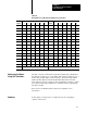
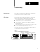
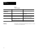
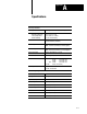
Table Of Contents
- 1791-6.5.1, Block I/O, User Manual
- Important User Information
- Summary of Changes
- Table of Contents
- 1 - Using This Manual
- 2 - Introducing Block I/O
- 3 - Installing Block I/O
- 4 - Configuring Your Block I/O for PLC Family Programmable Controllers
- 5 - Configuring Your Block I/O for SLC Controllers
- 6 - Troubleshooting
- A - Specifications
- Index
- Back Cover
Troubleshooting
Chapter 6
62
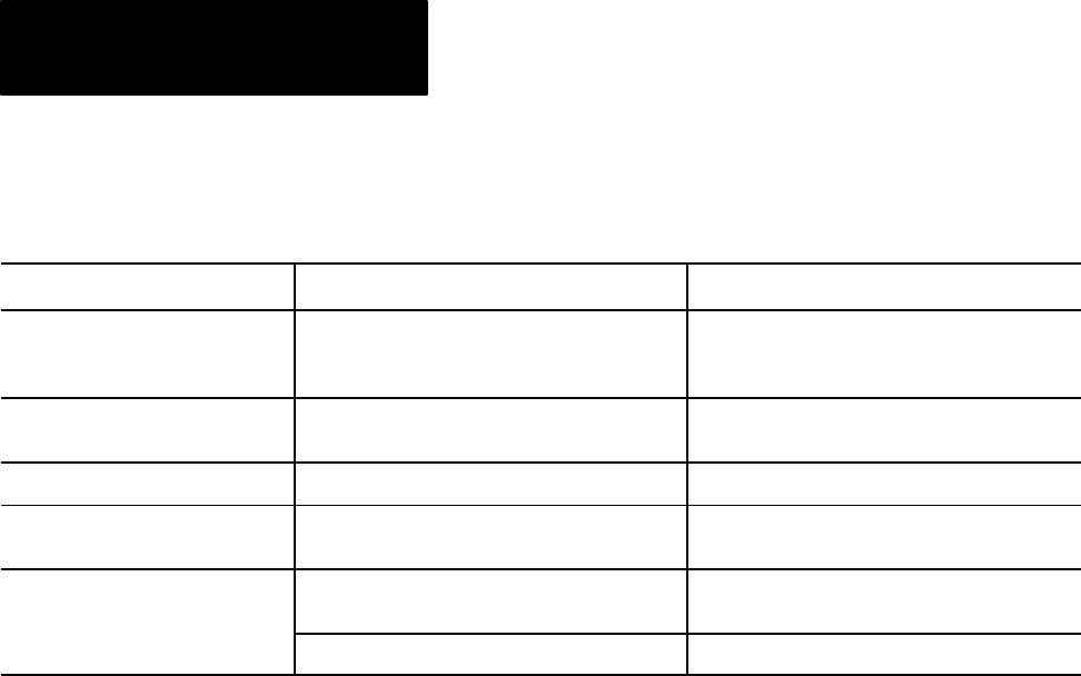
Table 6.A
Troubleshooting
Chart
Indication Probable Cause Corrective Action
Green COMM LED on
Red POWER LED on
I/O status LED on/off
Normal indication None required
Red POWER LED flashing Block failed self-test, or a major fault is detected. Cycle power to the block. If problem persists,
replace the block.
Red POWER LED off No 24V dc power connected, or hardware fault. Check 24V dc power to block
Green COMM LED off No communication with processor, scanner etc. Check that power LED is on. Make sure that
proper number of blocks are configured.
Green COMM LED flashing Reset command (or output disable bit for SLC) has
been issued by processor or scanner.
Check program. Correct as necessary.
SLC or programmable controller not in run mode. Place in run mode.
In this chapter you learned about the LED indicators and how to use them
to troubleshoot the block I/O module.
Summary