
USER MANUAL
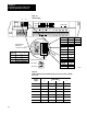
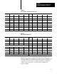
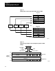
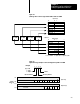

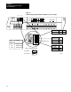
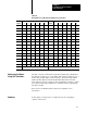
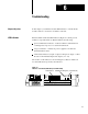
Table Of Contents
- 1791-6.5.1, Block I/O, User Manual
- Important User Information
- Summary of Changes
- Table of Contents
- 1 - Using This Manual
- 2 - Introducing Block I/O
- 3 - Installing Block I/O
- 4 - Configuring Your Block I/O for PLC Family Programmable Controllers
- 5 - Configuring Your Block I/O for SLC Controllers
- 6 - Troubleshooting
- A - Specifications
- Index
- Back Cover

Chapter
5
51
Configuring Your Block I/O for SLC
Controllers
In this chapter you will learn to identify block I/O switches and their
position.
Refer to publication 1747–ND012, Distributed I/O Scanner and Block, for
complete information on switch settings and addressing of the block I/O.
Each block I/O module has two 6–position DIP switches for setting:
block address
transmission (baud) rate
last state or reset
DH–485 termination
These switches are accessible by opening the door on the left side of the
module (Figure 5.1).
Chapter
Objectives
Setting the Configuration
Switches