
USER MANUAL
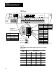
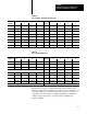
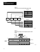
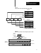
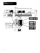
Table Of Contents
- 1791-6.5.1, Block I/O, User Manual
- Important User Information
- Summary of Changes
- Table of Contents
- 1 - Using This Manual
- 2 - Introducing Block I/O
- 3 - Installing Block I/O
- 4 - Configuring Your Block I/O for PLC Family Programmable Controllers
- 5 - Configuring Your Block I/O for SLC Controllers
- 6 - Troubleshooting
- A - Specifications
- Index
- Back Cover
Configuring Your Block I/O for PLC
Family Programmable Controllers
Chapter 4
45
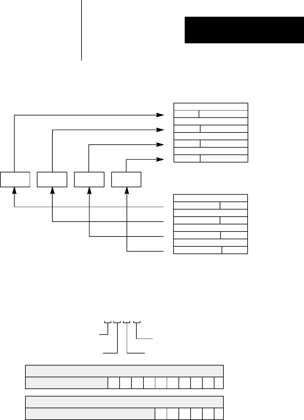
Figure 4.4
I/O Image T
able for One Assigned Rack Number with 1791-IOBB
017
Output Image
Input Image
Reserved
Reserved
Reserved
Reserved
Reserved
0
1
2
3
4
5
6
7
Reserved
Reserved
Reserved
710
017
Reserved
Reserved
Reserved
Reserved
Reserved
0
1
2
3
4
5
6
7
Reserved
Reserved
Reserved
710
1 I/O Rack
For 1791-IOBB - 11-0 input and 5-0 output image bits
1791-IOBB1791-IOBB1791-IOBB1791-IOBB
Figure 4.5
Input
T
able Usage Example for One Starting I/O Group with 1791-IOBB
11 10 7 6
Block Data
112
113
012
013
11107654321
Reserved
Reserved
54321
Reserved
Reserved
0
0
Starting
I/O
Group
2
Block Data
Input Image
Output Image
Type
of I/O
I/O Rack Number
I/O Group Number
I/O Bit
11200
1 = Input
0 = Output
Example