
USER MANUAL
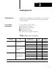
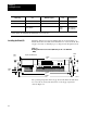
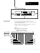
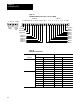
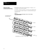
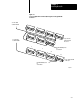
Table Of Contents
- 1791-6.5.1, Block I/O, User Manual
- Important User Information
- Summary of Changes
- Table of Contents
- 1 - Using This Manual
- 2 - Introducing Block I/O
- 3 - Installing Block I/O
- 4 - Configuring Your Block I/O for PLC Family Programmable Controllers
- 5 - Configuring Your Block I/O for SLC Controllers
- 6 - Troubleshooting
- A - Specifications
- Index
- Back Cover
Installing Block I/O
Chapter 3
34
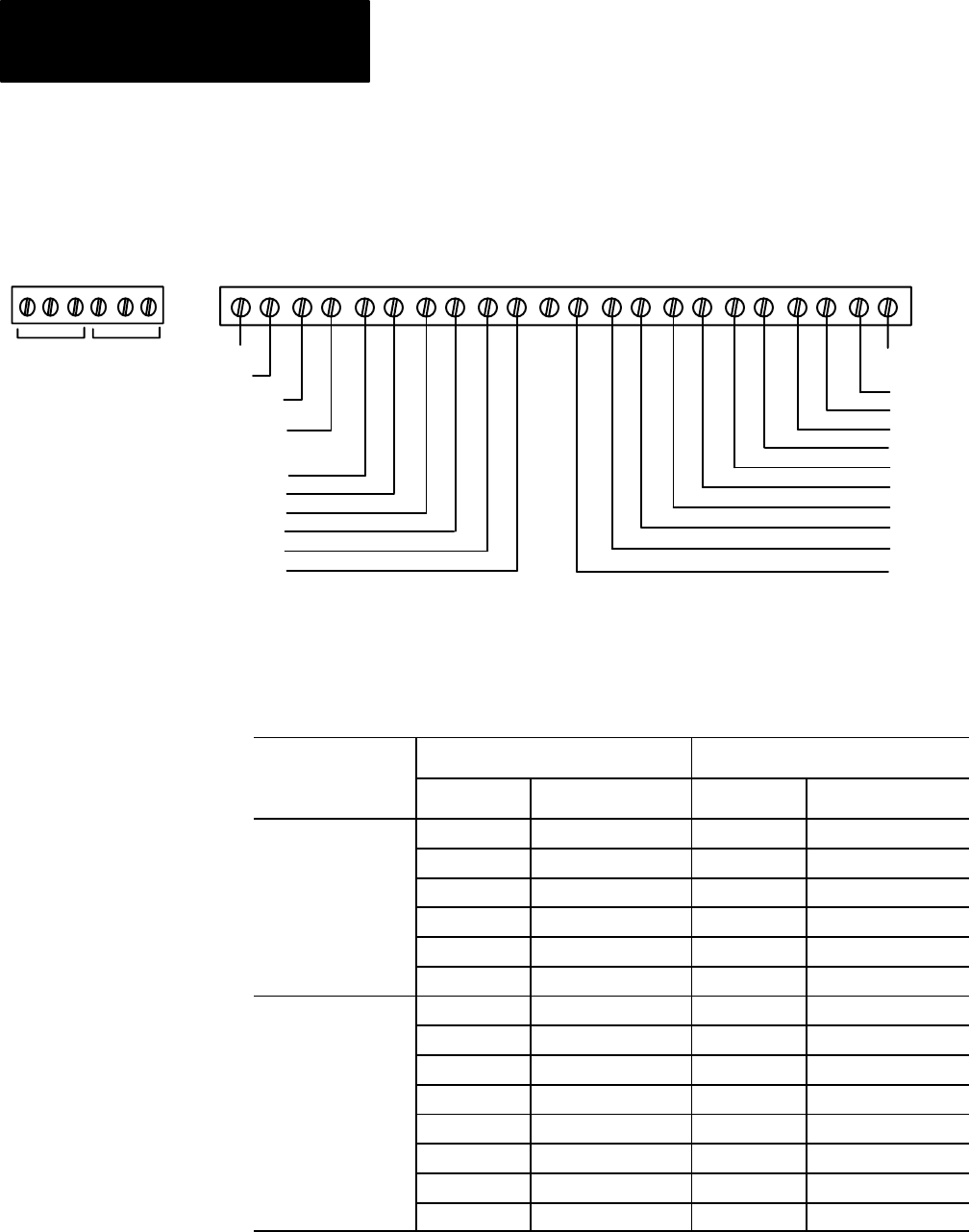
Figure 3.4
Input/Output
W
iring Connections for the 1791-IOBB
+24 DCN CGVDC O0 O1 O2 O3 O4 O5 I0 I1 I2 I3 I4 I5 I6 I7 I8 I9 COMNC
6 OUTPUTS
10 INPUTS
INPUT 9
INPUT 8
INPUT 7
INPUT 6
INPUT 5
INPUT 4
OUTPUT 0
OUTPUT 1
OUTPUT 2
OUTPUT 3
OUTPUT 4
OUTPUT 5
INPUT 3
INPUT 2
INPUT 1
INPUT 0
+24V dc
dc Neutral
Output +Vdc
Chassis Ground
Input Common
2 SHD B A COM1
Remote
I/O Link
DH-485
(for SLC
only)
Table 3.B
Wiring
Block Designations
1791-IOBA 1791-IOBB
Connector Designation Description Designation Description
Remote I/O Connector 1 Blue wire - RIO 1 Blue wire - RIO
2 Clear wire - RIO 2 Clear wire - RIO
SHD Shield - RIO SHD Shield - RIO
A DH-485 A A DH-485 A
B DH-485 B B DH-485 B
COM DH-485 Common COM DH-485 Common
I/O Connector +24 +24V dc +24 +24V dc
DCN dc neutral DCN dc neutral
CG Chassis ground CG Chassis ground
VDC Output supply VDC Output supply
O0 thru O7 Output 0 thru 7 O0 thru O5 Output 0 thru 5
NC No connection NC No connection
I0 thru I7 Input 0 thru 7 I0 thru I7 Input 0 thru 9
COM Input common COM Input common