
USER MANUAL
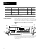
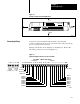
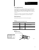
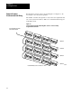
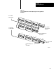
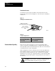
Table Of Contents
- 1791-6.5.1, Block I/O, User Manual
- Important User Information
- Summary of Changes
- Table of Contents
- 1 - Using This Manual
- 2 - Introducing Block I/O
- 3 - Installing Block I/O
- 4 - Configuring Your Block I/O for PLC Family Programmable Controllers
- 5 - Configuring Your Block I/O for SLC Controllers
- 6 - Troubleshooting
- A - Specifications
- Index
- Back Cover
Installing Block I/O
Chapter 3
33
Figure 3.2
Clearance
Required for Block I/O Modules
OUTPUT
INPUT
COMMPOWER
51mm
2"
51mm
2"
51mm
2"
51mm
2"
10830-I
Connections to the block I/O module are made to the removable
connectors which plug into the front of the block. The connector blocks are
keyed to prevent incorrect insertion.
Wiring for the block is shown in Figure 3.3 and Figure 3.4. Remote I/O
link wiring connections are shown in Figure 3.5.
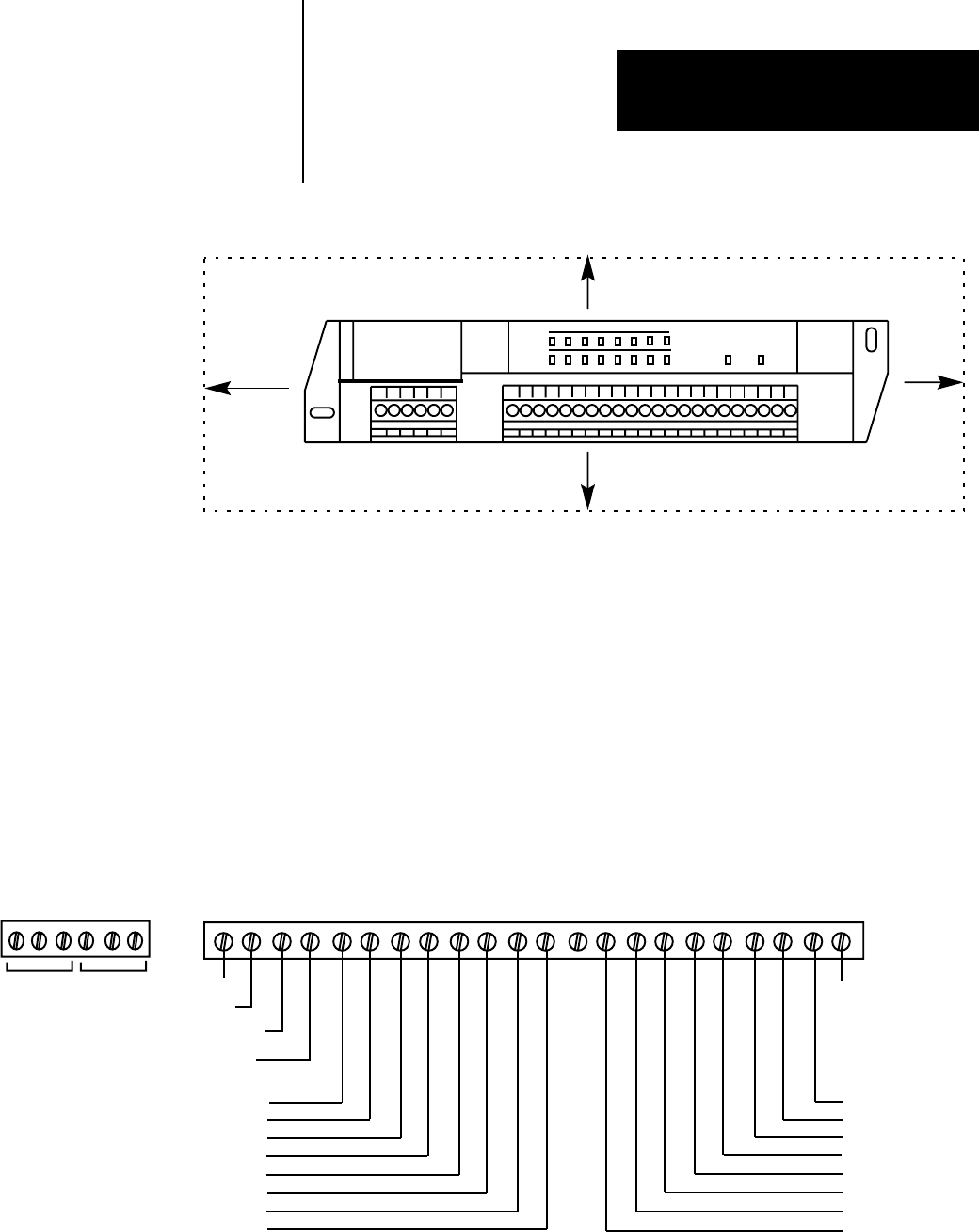
Figure 3.3
Input
and Output Connections for the 1791-IOBA
+24DCNCGVDCO0O1O2O3O4O5 I0 I1I2 I3I4 I5I6 I7COMNC
8 OUTPUTS
8 INPUTS
INPUT 7
INPUT 6
INPUT 5
INPUT 4
INPUT 3
INPUT 2
OUTPUT 0
OUTPUT 1
OUTPUT 2
OUTPUT 3
OUTPUT 4
OUTPUT 5
INPUT 1
INPUT 0
+24V dc
dc Neutral
Output +Vdc
Chassis Ground
Input Common
O6O7
OUTPUT 6
OUTPUT 7
2SHD BACOM1
Remote
I/O Link
(see Figure 3.5)
DH-485
(for SLC
only)
1791-IOBA
- 8 inputs and 8 outputs
10831-I
Connecting
W
iring