
USER MANUAL

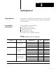
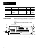
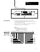
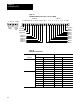
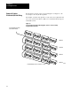
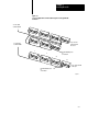
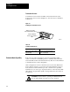
Table Of Contents
- 1791-6.5.1, Block I/O, User Manual
- Important User Information
- Summary of Changes
- Table of Contents
- 1 - Using This Manual
- 2 - Introducing Block I/O
- 3 - Installing Block I/O
- 4 - Configuring Your Block I/O for PLC Family Programmable Controllers
- 5 - Configuring Your Block I/O for SLC Controllers
- 6 - Troubleshooting
- A - Specifications
- Index
- Back Cover
Chapter
3
31
Installing Block I/O
In this chapter you will learn how to mount the block, connect the remote
I/O link, connect the input and output wiring to the block, and terminate
the remote I/O link.
Before installation, you must determine:
the number of blocks desired
the total distance of the installation
transmission rate desired
if external fuses are required
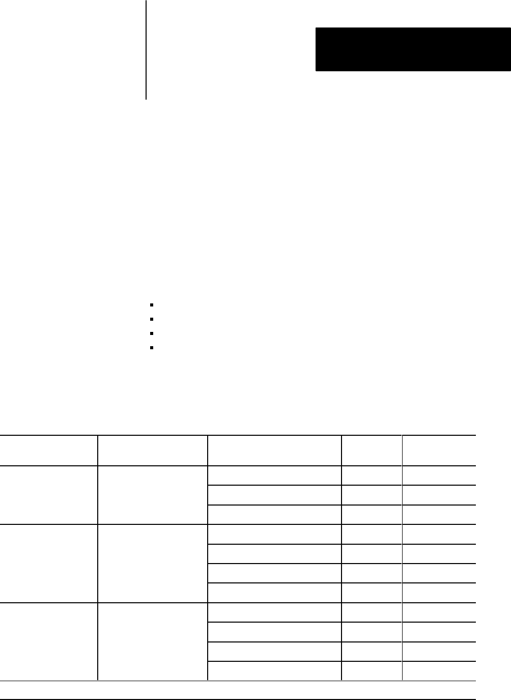
Refer to Table 3.A for acceptable combinations.
Table 3.A
Acceptable
Combinations of Processor and Block I/O
When using and Maximum Capacity
Baud Rate
Used
Maximum
Network Distance
PLC-2 family 16 blocks with 150 ohm terminator 57.6K 10,000 cable-feet
Any scanner module
28 blocks with 82 ohm terminator 57.6K 10,000 cable-feet
28 blocks with 82 ohm terminator 115.2K 5,000 cable-feet
PLC-3 family 16 blocks with 150 ohm terminator 57.6K 10,000 cable-feet
1775S4A, S4B, S5, SR
32 blocks with 82 ohm terminator 57.6K 10,000 cable-feet
1775 S4A
,
S4B
,
S5
,
SR
or SR5 module
32 blocks with 82 ohm terminator 115.2K 5,000 cable-feet
32 blocks with 82 ohm terminator 230.4K 2,500 cable-feet
PLC-5 family 16 blocks with 150 ohm terminator 57.6K 10,000 cable-feet
Note: PLC5250 requires a
32 blocks with 82 ohm terminator 57.6K 10,000 cable-feet
Note:
PLC 5250
requires
a
5150RS remote scanner
32 blocks with 82 ohm terminator 115.2K 5,000 cable-feet
32 blocks with 82 ohm terminator 230.4K 2,500 cable-feet
TABLE CONTINUED ON NEXT PAGE
Chapter
Objectives
Pre-installation
Considerations