Block I/O Cat. No.
Important User Information Because of the variety of uses for this product and because of the differences between solid state products and electromechanical products, those responsible for applying and using this product must satisfy themselves as to the acceptability of each application and use of this product. For more information, refer to publication SGI–1.1 (Safety Guidelines For The Application, Installation and Maintenance of Solid State Control).
Summary of Changes Summary of Changes Summary of Changes This issue of the manual contains new information and updated information. New Information This version of the manual includes the addition of the 1791–IOBB block I/O module. The 1791–IOBB block I/O module has: 10 inputs 6 outputs Updated Information This manual also includes the addition of information previously included in publication 1791–6.5.1–DU1, the documentation update which covered the 1791–IOBB block I/O module.
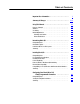
Table of Contents Important User Information . . . . . . . . . . . . . . . . . . . . . . . . I Summary of Changes . . . . . . . . . . . . . . . . . . . . . . . . . . . . S-1 Using This Manual . . . . . . . . . . . . . . . . . . . . . . . . . . . . . . . 1 1 Purpose of Manual . . . . . . . . . . . . . . . . . . . . . . . . . . . . . . . . . . . Audience . . . . . . . . . . . . . . . . . . . . . . . . . . . . . . . . . . . . . . . . . . Vocabulary . . . . . . . . . . . . . . . . . . . . . . . . . . . .
ii Table of Contents Configuring Your Block I/O for SLC Controllers . . . . . . . . . 5 1 Chapter Objectives . . . . . . . . . . . . . . . . . . . . . . . . . . . . . . . . . . . Setting the Configuration Switches . . . . . . . . . . . . . . . . . . . . . . . . Addressing the Blocks Using SLC Controllers . . . . . . . . . . . . . . . . Summary . . . . . . . . . . . . . . . . . . . . . . . . . . . . . . . . . . . . . . . . . 5 1 5 1 5 3 5 3 Troubleshooting . . . . . . . . . . . . . . . . . . . . . . .
Chapter 1 Using This Manual Purpose of Manual This manual shows you how to use your Block I/O with an Allen–Bradley programmable controller. It helps you install, program and troubleshoot your module. Audience You must be able to program and operate an Allen–Bradley programmable controller (PLC) to make efficient use of Block I/O modules. We assume that you know how to do this in this manual.
Chapter 1 Using This Manual Warnings and Cautions This manual may contain warnings and cautions. A warning tells where you may be injured if you use your equipment improperly. Cautions tell where equipment may be damaged from misuse. You should read and understand cautions and warnings before performing the procedures they precede. Related Publications 1 2 For a list of publications with information on Allen–Bradley programmable controller products, consult our publication index (SD499).
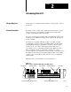
Chapter 2 Introducing Block I/O Chapter Objectives In this chapter you will learn what block I/O is, and its features, and how it functions. General Description Block I/O consists of small, self–contained remote I/O devices complete with power supply, programmable controller interface, input/output connections and signal conditioning circuitry. Two types of block I/O are available. The 1791–IOBA has 8 inputs and 8 outputs; the 1791–IOBB has 10 inputs and 6 outputs.
Chapter 2 Introducing Block I/O Wiring Connectors – The remote I/O link connector and input/output connector are removable for easy connection of wiring. Switch Assemblies – Two DIP switches are provided for setting the I/O rack number, starting I/O group, transmission rate, last chassis, last state and DH–485 terminator. Status Indicators – LED indicators are provided for communication, power and input/output status. These provide a visual indication for aid in troubleshooting.
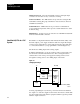
Chapter 2 Introducing Block I/O Figure 2.3 Sourcing Output Example Block I/O +V DC Power Supply Fuse Field Device Fuse Field Device -V GND Common Bus 10827-I You connect the block I/O to your remote I/O link as you would any other device (Figure 2.4). The block looks like a 1/4 I/O rack to the processor, and uses 2 words of input image table memory and 2 words of output image table memory. The block is addressed directly on the remote I/O link.
Chapter 2 Introducing Block I/O Summary 2 4 In this chapter you learned what block I/O is, its features and how it functions.
Chapter 3 Installing Block I/O Chapter Objectives In this chapter you will learn how to mount the block, connect the remote I/O link, connect the input and output wiring to the block, and terminate the remote I/O link. Pre-installation Considerations Before installation, you must determine: the number of blocks desired the total distance of the installation transmission rate desired if external fuses are required Refer to Table 3.A for acceptable combinations. Table 3.
Chapter 3 Installing Block I/O When using and Maximum Capacity Baud Rate Used Maximum Network Distance SLC-5/01 Controller 1747-DSN Scanner module* 7 blocks 230.4K 2,500 cable-feet SLC-5/02 Controller 1747-DSN Scanner module* 30 blocks 230.4K 2,500 cable-feet SLC-5/02 Controller 1747-SN Remote I/O Scanner Module* 16 blocks 57.6K 115.2K 230.
Chapter 3 Installing Block I/O Figure 3.2 Clearance Required for Block I/O Modules 51mm 2" OUTPUT COMM POWER INPUT 51mm 2" 51mm 2" 51mm 2" 10830-I Connecting Wiring Connections to the block I/O module are made to the removable connectors which plug into the front of the block. The connector blocks are keyed to prevent incorrect insertion. Wiring for the block is shown in Figure 3.3 and Figure 3.4. Remote I/O link wiring connections are shown in Figure 3.5. Figure 3.
Chapter 3 Installing Block I/O Figure 3.4 Input/Output Wiring Connections for the 1791-IOBB 10 INPUTS 6 OUTPUTS 2 SHD 1 B A COM Remote I/O Link DH-485 (for SLC only) +24 DCN CGVDC O0 O1 O2 O3 O4 O5 NC I0 I1 I2 I3 I4 I5 I6 I7 I8 I9 COM +24V dc dc Neutral Chassis Ground Input Common INPUT 9 INPUT 8 INPUT 7 INPUT 6 INPUT 5 INPUT 4 INPUT 3 INPUT 2 INPUT 1 INPUT 0 Output +Vdc OUTPUT 0 OUTPUT 1 OUTPUT 2 OUTPUT 3 OUTPUT 4 OUTPUT 5 Table 3.
Chapter 3 Installing Block I/O Power Supply Requirements An external 24V dc power supply is required to power the block. Total current required to power the block is equal to 200mA plus an inrush of 5.5A for 10µsec for each block. The supply must be able to source an additional 100mA plus an inrush current of 400mA when a peripheral is connected. In addition, the external power supply should have current limiting capabilities. The voltage range must not exceed 20.5–27.6V dc.
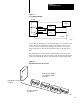
Chapter 3 Installing Block I/O Remote I/O Link or Distributed I/O Link Wiring Blocks must be wired in series as shown in Figure 3.6 or Figure 3.7. Do not attempt to wire any block in parallel. The number of blocks used depends not only on the user requirements but also on the system used. Refer to Table 3.A for maximum block usage for individual systems. Figure 3.
Chapter 3 Installing Block I/O Figure 3.7 Series Configurations for Block I/O Using the SLC Programmable Controller To 1747-DSN Scanner Module Up to 7 blocks using SLC-5/01 Processor To 1747-DSN Scanner Module 1 Install terminating resis tor on last block. 2 29 30 Install terminating resis tor on last block.
Chapter 3 Installing Block I/O Termination Resistor A termination resistor must be installed on the last block in the series. Connect the resistor as shown in Figure 3.8. Use the resistor as identified in Table 3.D. Figure 3.8 Installing the Termination Resistor Tighten screw to clamp wires and termination resistor. Connect termination resistor across terminals 1 and 2 Termination Resistor 10835-I Table 3.
Chapter 3 Installing Block I/O Compatibility of 1771 I/O Products with Extended Node Numbers Certain products are not compatible with extended node capabilities obtained with the use of 82 ohm terminators. The following table lists those products that are not compatible.
Chapter 4 Configuring Your Block I/O for PLC Family Programmable Controllers Chapter Objectives In this chapter you will learn how to configure your block I/O when used with PLC family programmable controllers.
Chapter 4 Configuring Your Block I/O for PLC Family Programmable Controllers Figure 4.1 Switch Settings S1 S2 OUTPUT COMM POWER INPUT Baud Rate 0 2 4 6 Switch 1 2 On (Closed) On (Closed) Off (Open) On (Closed) On (Closed) Off (Open) Off (Open) Off (Open) OPEN 3 4 5 6 OPEN Last State 4 Reset to 0 Off (Open) Hold last state On (Closed) Not Use d Last Chassis Switch as viewed from this end.
Chapter 4 Configuring Your Block I/O for PLC Family Programmable Controllers Table 4.
Chapter 4 Configuring Your Block I/O for PLC Family Programmable Controllers Figure 4.2 I/O Image Table for One Assigned Rack Number with 1791-IOBA Input Image 10 7 Reserved Reserved Reserved Reserved Reserved Reserved Reserved Reserved 17 0 1 2 3 4 5 6 7 1791-IOBA 1791-IOBA 1791-IOBA Rack 1 1791-IOBA Output Image 10 7 Reserved Reserved Reserved Reserved Reserved Reserved Reserved Reserved 17 0 1 2 3 4 5 6 7 0 0 For 1791-IOBA - 7-0 input and 7-0 output image bits 10837-I Figure 4.
Chapter 4 Configuring Your Block I/O for PLC Family Programmable Controllers Figure 4.4 I/O Image Table for One Assigned Rack Number with 1791-IOBB Input Image 10 7 Reserved Reserved Reserved Reserved Reserved Reserved Reserved Reserved 17 0 1 2 3 4 5 6 7 1791-IOBB 1791-IOBB 1791-IOBB 1 I/O Rack 1791-IOBB Output Image 10 7 Reserved Reserved Reserved Reserved Reserved Reserved Reserved Reserved 17 0 1 2 3 4 5 6 7 0 0 For 1791-IOBB - 11-0 input and 5-0 output image bits Figure 4.
Chapter 4 Configuring Your Block I/O for PLC Family Programmable Controllers Summary 4 6 In this chapter you learned how to set the configuration switches and address the block I/O. You also learned about input and output image use in memory.
Chapter 5 Configuring Your Block I/O for SLC Controllers Chapter Objectives In this chapter you will learn to identify block I/O switches and their position. Refer to publication 1747–ND012, Distributed I/O Scanner and Block, for complete information on switch settings and addressing of the block I/O.
Chapter 5 Configuring Your Block I/O for SLC Controllers Figure 5.1 Switch Settings for Block I/O when used with the SLC 500 Controller S1 S2 OUTPUT COMM POWER INPUT 1-7 1-15 17-31 Switches 1-6 100000 to 111000 100000 to 111100 100010 to 111110 OPEN 3 4 5 6 OPEN S2 1 2 Block Addresses 1 2 3 4 5 6 S1 Switch as viewed from this end. Baud Rate 5 6 230.
Chapter 5 Configuring Your Block I/O for SLC Controllers Table 5.
Chapter 6 Troubleshooting Chapter Objectives In this chapter you will learn about the LED indicators on the block I/O module, and how to use them to troubleshoot the unit. LED Indicators Each block I/O module has LED indicators (Figure 6.1) which provide indication of specific functions. Each module has the following: green communication indicator – indicates whether communication is occurring between processor or scanner and the block.
Chapter 6 Troubleshooting Table 6.A Troubleshooting Chart Indication Probable Cause Corrective Action Green COMM LED on Red POWER LED on I/O status LED on/off Normal indication None required Red POWER LED flashing Block failed self-test, or a major fault is detected. Cycle power to the block. If problem persists, replace the block. Red POWER LED off No 24V dc power connected, or hardware fault. Check 24V dc power to block Green COMM LED off No communication with processor, scanner etc.
Appendix A Specifications General Specifications External power 200mA @ 24V dc; initial surge 5.5A for 10µsec Environmental Conditions Operating Temperature Storage Temperature Relative Humidity 32 to 131oF (0 to 55oC) -40 to 185oF (-40 to 85oC) 5 to 95% noncondensing Conductors Wire Size 14 gauge stranded (maximum) 3/64 inch insulation (maximum) Power Dissipation IOBA: 13.42 Watts (maximum); 9.46 Watts (typical) IOBB: 12.39 Watts (maximum); 8.73 Watts (typical) Thermal Dissipation IOBA: 45.
Appendix A Specifications 1791-IOBA Output Specifications Number of outputs 8 Output type Source Rated output voltage 10 to 30V dc Maximum on-state voltage drop 1.5V dc @ 25oC Maximum on-state current 0.5A Minimum on-state current 15mA Surge Current 3.0A for 10ms (maximum), 1 pulse per second max. Off-state voltage 30V dc (maximum) Off-state leakage current 0.5mA (maximum) Turn on time 0.
Appendix A Specifications 1791-IOBB Output Specifications Number of outputs 6 Output type Source Rated output voltage 10 to 30V dc Maximum on-state voltage drop 1.5V dc @ 25oC Maximum on-state current 0.5A Minimum on-state current 15mA Surge Current (maximum) 3.0A for 10ms (max), 1 pulse per second max. Off-state voltage 30V dc (maximum) Off-state leakage current 0.5mA (maximum) Turn on time 0.
Index B block addressing, SLC, 5 3 C combinations, acceptable processor and block I/O, 3 1 compatibility, extended node numbers, 3 9 M mounting dimensions, 3 2 P power supply requirements, 3 5 R configuration switches, 4 1 SLC, 5 1 related publications, 1 2 connecting block I/O, in a PLC system, 2 3 remote I/O link connector, 2 2 connecting wiring, 3 3 1791-IOBA, 3 3 1791-IOBB, 3 4 remote I/O link wiring, 3 6 D description, 2 1 DH-485 port, 2 2 E extended node capability, 3 8 S series connecti
With offices in major cities worldwide WORLD HEADQUARTERS Allen-Bradley 1201 South Second Street Milwaukee, WI 53204 USA Tel: (414) 382-2000 Telex: 43 11 016 FAX: (414) 382-4444 EUROPE/MIDDLE EAST/AFRICA HEADQUARTERS Allen-Bradley Europa B.V. Amsterdamseweg 15 1422 AC Uithoorn The Netherlands Tel: (31) 2975/60611 Telex: (844) 18042 FAX: (31) 2975/60222 Publication 1791–6.5.1 – November 1991 Supersedes publication 1791–6.5.1 – August 1991 and 1791–6.5.