
Manual

Troubleshooting
Chapter 4
4-2
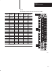
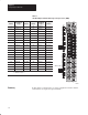
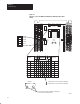
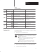
Figure 4.1
Indicators
on the 1791-IOBX and -IOVX Block I/O Modules (PLC labels
shown)
00
01
02
03
04
05
06
07
10
11
12
13
14
15
16
17
NC
COM
DISPLAY
SELECT
INPUT
OUTPUT
POWER
ACTIVE
COMM
FUSE
RACK
ADDR
87654321
CONFIGURATION
SWITCHES
00
01
02
03
04
05
06
07
10
11
12
COM
00
01
02
03
04
05
06
07
10
11
12
13
14
15
16
17
COM
+VDC
00
01
02
03
04
05
06
07
10
11
+VDC
POWER
ACTIVE
COMM
FUSE
00
01
02
03
04
05
06
07
10
11
12
13
14
15
16
17
00
01
02
03
04
05
06
07
10
11
12
13
14
15
16
17
0:1 2:3GROUP
LED
0:1 2:3
INPUT
OUTPUT
DISPLAY
SELECT
INPUT
OUTPUT
00
01
02
03
04
05
06
07
10
11
12
13
14
15
16
17
00
01
02
03
04
05
06
07
10
11
12
13
14
15
16
17
indicates LED off - lower 32 bits are displayed
indicates LED on - upper 32 bits are displayed
Press Input and Output pushbuttons simultaneously
to reset Processor Restart Lockout.
10943-I