
Manual


Configuring
Y
our Block I/O
Chapter 3
3-5
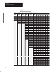
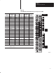
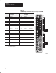
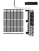
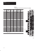
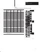
Rack Address Switch Position
PLC-3
Rack
Number
PLC-5/250
Rack
Number
PLC-5
Rack
Number
PLC-2
Rack
Number
1771-SN
Rack
Number
1747-SN
Rack
Number
123456
PLC-3
Rack
Number
PLC-5/250
Rack
Number
PLC-5
Rack
Number
PLC-2
Rack
Number
1771-SN
Rack
Number
1747-SN
Rack
Number
Rack
63
1 1 0 0 1 1
Rack 64
1 1 0 1 0 0
Rack 65
1 1 0 1 0 1
Rack 66
1 1 0 1 1 0
Rack 67
1 1 0 1 1 1
Rack 70
1 1 1 0 0 0
Rack 71
1 1 1 0 0 1
Rack 72
1 1 1 0 1 0
Rack 73
1 1 1 0 1 1
Rack 74
1 1 1 1 0 0
Rack 75
1 1 1 1 0 1
Rack 76
1 1 1 1 1 0
Not V
alid 1 1 1 1 1 1
Rack address 77 is an illegal configuration.
PLC-5/1
1 processors can scan rack 03.
PLC-5/15 and PLC-5/20 processors can scan racks 01-03.
PLC-5/25 and PLC-5/30 processors can scan racks 01-07.
PLC-5/40 and PLC-5/40L processors can scan racks 01-17.
PLC-5/60 and PLC-5/60L processors can scan racks 01-27.
PLC-5/250 processors can scan racks 00-37.
PLC-3 processors can scan racks 00-76.
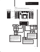
Each block uses 4 words of output image table memory and 4 words of
input image table memory. Each block occupies 1/2 rack of data table, with
2 blocks comprising 1 logical rack. Image table usage for one assigned
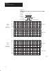
rack number is shown in Figure 3.3. An example of image table usage is
shown in Figure 3.4.
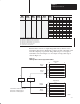
Figure 3.3
I/O
Image T
able for One Assigned Rack Number
017
Output Image
Input Image
0
1
2
3
4
5
6
7
710
017
0
1
2
3
4
5
6
7
710
1791-IOVX1791-IOBX
Rack 1
2 1791-IOBX or 1791-IOVX per rack
1st 1/2 rack = module group 0-3
2nd 1/2 rack = module group 4-7
Block 1
Inputs
Block 2
Inputs
Block 1
Outputs
Block 2
Outputs
1
2
10933-I