
USER MANUAL Manual

00
01
02
03
04
05
06
07
10
11
12
13
14
15
16
17
NC
COM
00
01
02
03
04
05
06
07
10
11
12
13
14
15
16
17
NC
COM
NC
1
0
INPUT
1
2
36 37
10935I
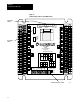
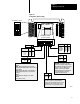
Configuring Your Block I/O
Chapter 3
3-7
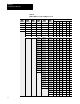
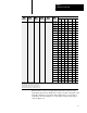
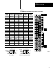
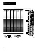
Table 3.B
1791IOBW
Input T
erminal Addressing for Groups 0 and 1 (TRM1)
Terminal
Number
Input
Assignment
Group 0
Program
Address
Terminal
Number
Input
Assignment
Group 1
Program
Address
1 Common A 19 Common B
2 Input 00 1XY00 20 Input 00 1X(Y+1)00
3 Input 01 1XY01 21 Input 01 1X(Y+1)01
4 Input 02 1XY02 22 Input 02 1X(Y+1)02
5 Input 03 1XY03 23 Input 03 1X(Y+1)03
6 Input 04 1XY04 24 Input 04 1X(Y+1)04
7 Input 05 1XY05 25 Input 05 1X(Y+1)05
8 Input 06 1XY06 26 Input 06 1X(Y+1)06
9 Input 07 1XY07 27 Input 07 1X(Y+1)07
10 Input 10 1XY10 28 Input 10 1X(Y+1)10
11 Input 11 1XY11 29 Input 11 1X(Y+1)11
12 Input 12 1XY12 30 Input 12 1X(Y+1)12
13 Input 13 1XY13 31 Input 13 1X(Y+1)13
14 Input 14 1XY14 32 Input 14 1X(Y+1)14
15 Input 15 1XY15 33 Input 15 1X(Y+1)15
16 Input 16 1XY16 34 Input 16 1X(Y+1)16
17 Input 17 1XY17 35 Input 17 1X(Y+1)17
18 N.C. 36 N.C.
37 N.C.
Where: X = Rack Number (1, 2, 3 ...)
Y = Module Group (0, 2, 4, 6)
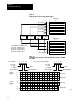
Type
of I/O
I/O Rack
Number
I/O Group
Number
I/O Bit
1 XY00
1 = Input
0 = Output
PLC2 Example
Type
of I/O
I/O Rack
Number
I/O Group
Number
I/O Bit
I XY00
I = Input
O = Output
PLC3, PLC5, PLC5/250 Example
NOTE: